Excelics
EFA080A
DATA SHEET
Low Distortion GaAs Power FET
∑
+26.0dBm TYPICAL OUTPUT POWER
∑
10.0dB TYPICAL POWER GAIN AT 12GHz
∑
0.3 X 800 MICRON RECESSED "MUSHROOM" GATE
∑
Si
3
N
4
PASSIVATION
∑
ADVANCED EPITAXIAL DOPING PROFILE
PROVIDES HIGH POWER EFFICIENCY,
LINEARITY AND RELIABILITY
∑
Idss SORTED IN 15mA PER BIN RANGE
ELECTRICAL CHARACTERISTICS (T
a
= 25
O
C)
SYMBOLS PARAMETERS/TEST
CONDITIONS MIN
TYP
MAX
UNIT
P
1dB
Output Power at 1dB Compression f=12GHz
Vds=8V, Ids=50% Idss f=18GHz
24.0 26.0
26.0
dBm
G
1dB
Gain at 1dB Compression f=12GHz
Vds=8V, Ids=50% Idss f=18GHz
8.0 10.0
7.5
dB
PAE
Power Added Efficiency at 1dB Compression
Vds=8V, Ids=50% Idss f=12GHz
35
%
Idss
Saturated Drain Current Vds=3V, Vgs=0V
130
210
300
mA
Gm
Transconductance Vds=3V, Vgs=0V
90
120
mS
Vp
Pinch-off Voltage Vds=3V, Ids=2.0mA
-2.0
-3.5
V
BVgd
Drain Breakdown Voltage Igd=1.0mA
-12
-15
V
BVgs
Source Breakdown Voltage Igs=1.0mA
-7
-14
V
Rth
Thermal Resistance (Au-Sn Eutectic Attach)
55
o
C/W
MAXIMUM RATINGS AT 25
O
C
SYMBOLS PARAMETERS ABSOLUTE
1
CONTINUOUS
2
Vds
Drain-Source Voltage
12V
8V
Vgs
Gate-Source Voltage
-8V
-4V
Ids
Drain Current
Idss
260mA
Igsf
Forward Gate Current
20mA
4mA
Pin
Input Power
25dBm
@ 3dB Compression
Tch
Channel Temperature
175
o
C
150
o
C
Tstg
Storage Temperature
-65/175
o
C
-65/150
o
C
Pt
Total Power Dissipation
2.5 W
2.1 W
Note: 1. Exceeding any of the above ratings may result in permanent damage.
2. Exceeding any of the above ratings may reduce MTTF below design goals.
Excelics Semiconductor, Inc., 2908 Scott Blvd., Santa Clara, CA 95054
Phone: (408) 970-8664 Fax: (408) 970-8998 Web Site: www.excelics.com
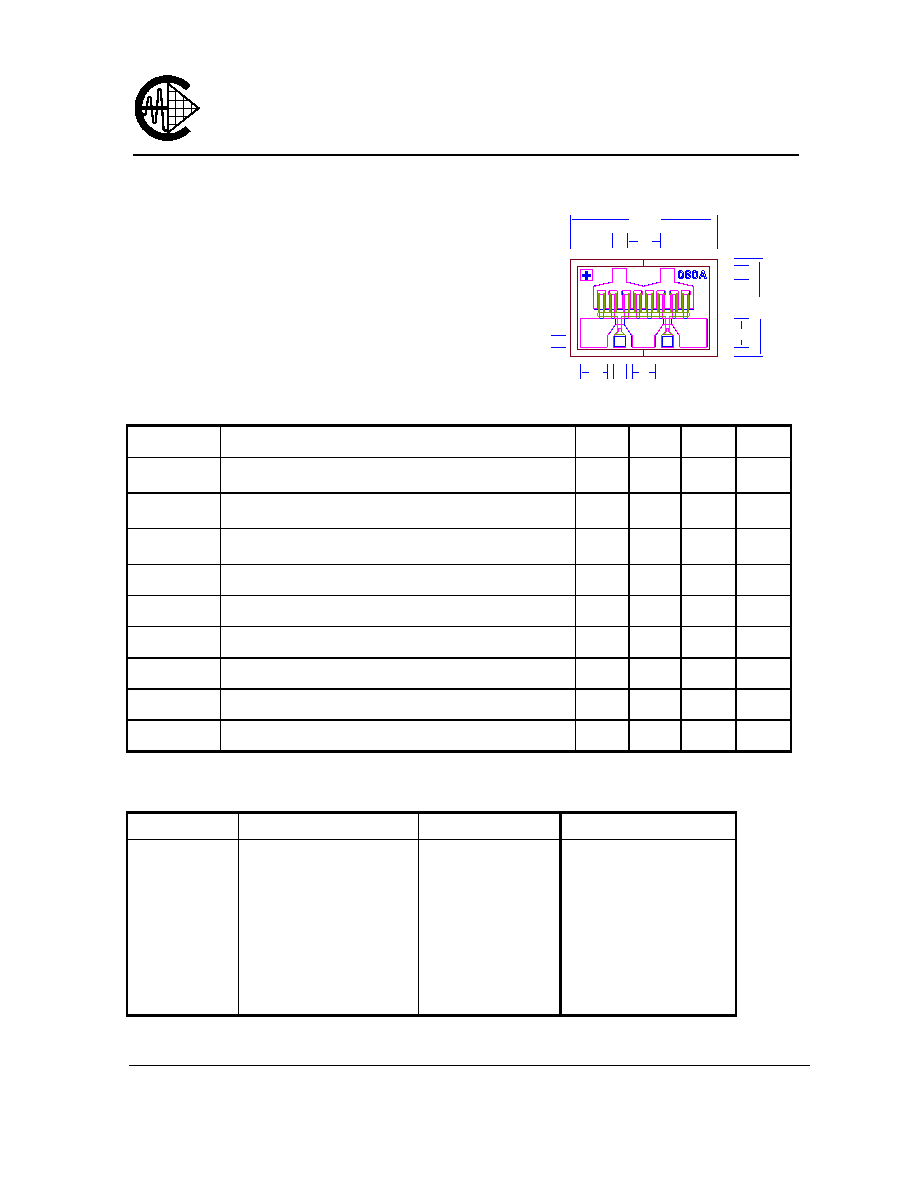
Chip Thickness: 75
±
13 microns
All Dimensions In Microns
50
48
100
50
95
40
340
510
116
80
D
D
G
G
S
S
S

EFA080A
DATA SHEET
Low Distortion GaAs Power FET
S-PARAMETERS
8V, 1/2 Idss
FREQ --- S11 --- --- S21 --- --- S12 --- --- S22 ---
(GHz) MAG ANG MAG ANG MAG ANG MAG ANG
1.0 0.983 -38.9 6.602 158.2 0.029 65.4 0.421 -24.5
2.0 0.949 -71.6 5.927 135.8 0.050 49.2 0.380 -45.7
3.0 0.916 -96.5 4.998 118.0 0.061 36.4 0.343 -62.4
4.0 0.894 -115.4 4.191 104.1 0.066 27.2 0.326 -75.6
5.0 0.879 -130.5 3.536 92.2 0.068 19.6 0.327 -87.3
6.0 0.873 -140.5 3.028 82.8 0.069 14.5 0.339 -95.6
7.0 0.871 -148.3 2.628 74.6 0.068 10.3 0.359 -102.4
8.0 0.869 -154.1 2.311 67.5 0.067 7.4 0.382 -107.5
9.0 0.872 -158.8 2.058 61.1 0.065 3.8 0.408 -111.9
10.0 0.872 -162.7 1.857 55.2 0.063 3.0 0.433 -115.1
11.0 0.873 -166.5 1.689 49.5 0.061 1.8 0.457 -118.4
12.0 0.876 -169.7 1.557 43.9 0.060 1.0 0.478 -121.4
13.0 0.879 -173.3 1.446 38.4 0.058 -0.9 0.495 -124.4
14.0 0.880 -177.4 1.356 32.9 0.059 -2.3 0.511 -127.6
15.0 0.882 178.3 1.276 27.2 0.057 -2.9 0.522 -131.2
16.0 0.886 173.2 1.207 20.9 0.057 -4.6 0.532 -135.3
17.0 0.889 168.2 1.141 14.6 0.057 -5.7 0.542 -140.3
18.0 0.892 162.8 1.075 8.3 0.058 -7.1 0.557 -145.3
19.0 0.897 157.9 1.010 1.7 0.057 -8.0 0.568 -151.5
20.0 0.905 153.4 0.949 -4.6 0.057 -9.8 0.585 -157.6
21.0 0.923 152.7 0.829 -9.6 0.053 -9.0 0.627 -165.3
22.0 0.928 150.2 0.769 -14.6 0.053 -9.5 0.650 -170.5
23.0 0.936 147.8 0.713 -19.7 0.052 -7.8 0.680 -174.4
24.0 0.939 146.5 0.664 -23.8 0.052 -5.4 0.706 -177.2
25.0 0.945 145.2 0.624 -27.3 0.053 -3.9 0.728 -179.7
26.0 0.944 144.7 0.592 -30.4 0.053 0.4 0.753 179.1
Note: The data included 0.7 mils diameter Au bonding wires:
2 gate wires, 15 mils each; 2 drain wires, 20 mils each; 6 source wires, 7 mils each.