FBI1.5G
4S1
400
FBI1.5D
4S1
200
FBI1.5J
4S1
600
FBI1.5K
4S1
800
FBI1.5M
4S1
1000
FBI1.5B
4S1
100
FBI1.5A
4S1
50
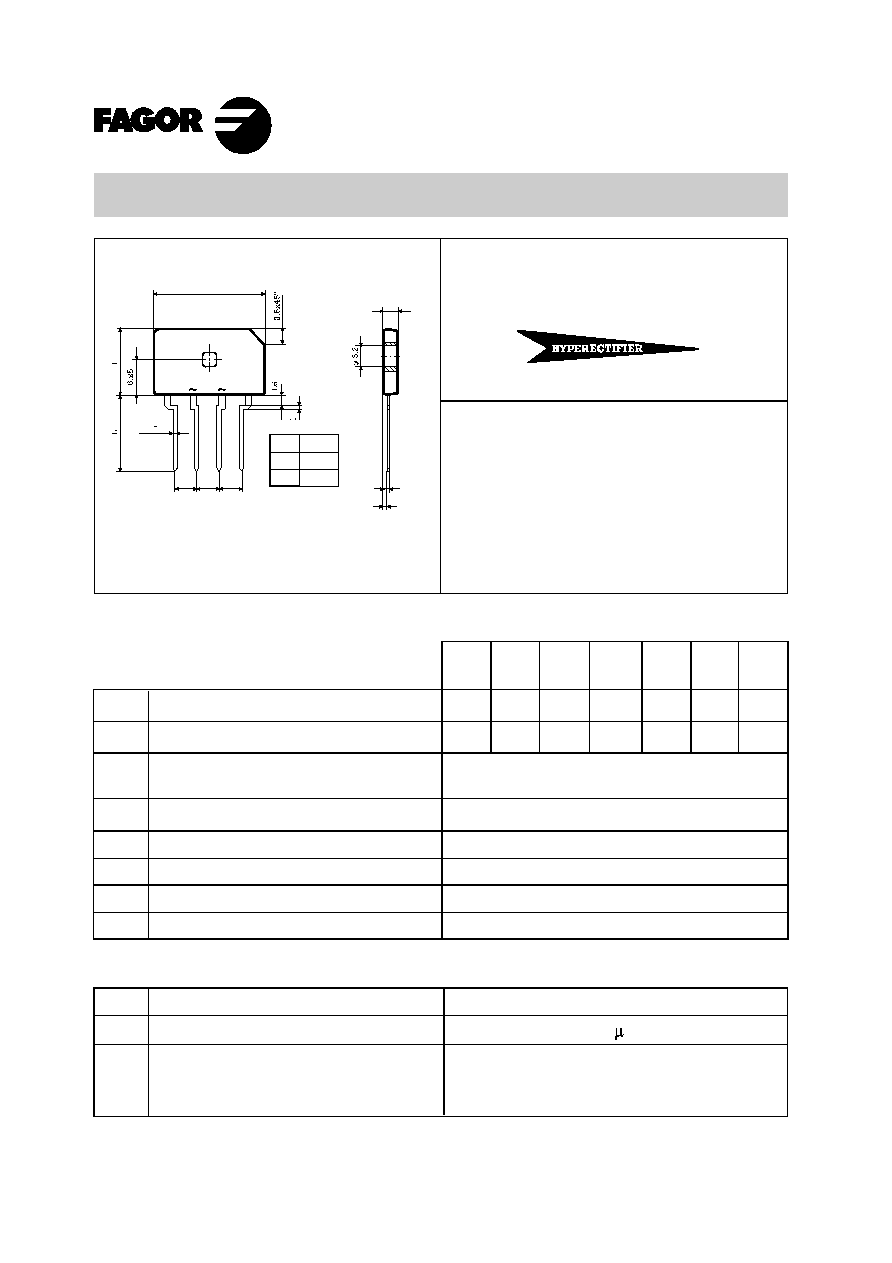
FBI1.5A4S1.......FBI1.5M4S1
1.5 Amp. Glass Passivated Bridge Rectifier
Dimensions in mm.
Maximum Ratings, according to IEC publication No. 134
Peak recurrent reverse voltage (V)
Max. Average forward current with heatsink
without heatsink
8.3 ms. peak forward surge current
Rating for fusing ( t<8.3 ms.)
Dielectric strength
(terminals to case, AC 1 min.)
Operating temperature range
Storage temperature range
I
FSM
I
2
t
V
DIS
T
j
T
stg
4.0 A at 65 ∫C
1.5 A at 25 ∫C
50 A
10 A
2
sec
1500 V
≠ 55 to + 150 ∞C
≠ 55 to +150 ∫C
Electrical Characteristics at Tamb = 25∞C
V
F
Max. forward voltage drop per element at I
F
= 1 A
I
R
1.0 V
Max. reverse current per element at V
RRM
Voltage
50 to 1000 V.
Current
1.5 A.
V
RRM
I
F(AV)
Plastic
Case
Æ
5 A
(Jedec Method)
MAXIMUM THERMAL RESISTANCE
Junction-Case. With Heatsink.
Junction-Ambient. Without Heatsink.
12 ∫C/W
45 ∫C/W
R
th (j-c)
R
th (j-a)
∑ Glass Passivated Junction Chips.
∑ UL recognized under component index file
number E130180.
∑ Lead and polarity identifications.
∑ Case: Molded Plastic.
∑ Ideal for printed circuit board (P.C.B.).
∑ The plastic material carries U/L recognition 94 V-O.
∑ Mounting Instructions
∑ High temperature soldering guaranteed: 260 ∫C ≠ 10 sc.
∑ Recommended mounting torque: 8 Kg.cm.
20
4
1
0.5
3.5
+
_
4
4
0.8
+ 0.05
L
suffix
13.5
7
≠4
Jan - 00
280
140
420
560
700
70
35
Maximum RMS voltage (V)
V
RMS
V
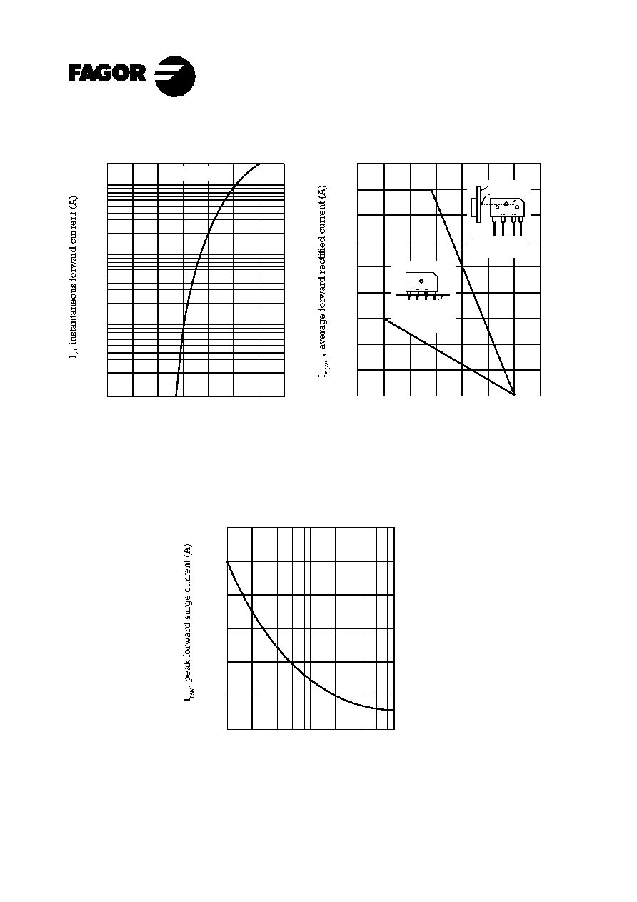
F
, instantaneous forward voltage (V)
0.6
1.0
1.4
0
0.1
1.0
10
Tamb = 25∞ C
Characteristic Curves
FBI1.5 - 4S1
Tamb, ambient temperature (∞C)
1
2
3
4
0
50
100
150 175
0
125
25
75
Number of cycles at 60 Hz.
10
100
0
10
20
30
40
50
60
TYPICAL FORWARD CHARACTERISTIC
FORWARD CURRENT DERATING CURVE
MAXIMUM NON-REPETITIVE PEAK
FORWARD SURGE CURRENT
1
heatsink
Tc
Tc
sine wave
R-load
on heatsink
+
_
on glass-epoxi substrate
soldering land 5 mm ¯
sine wave
R-load
free in air
P.C.B.
Jan - 00
+
_