Æ
∑ Glass Passivated Junction
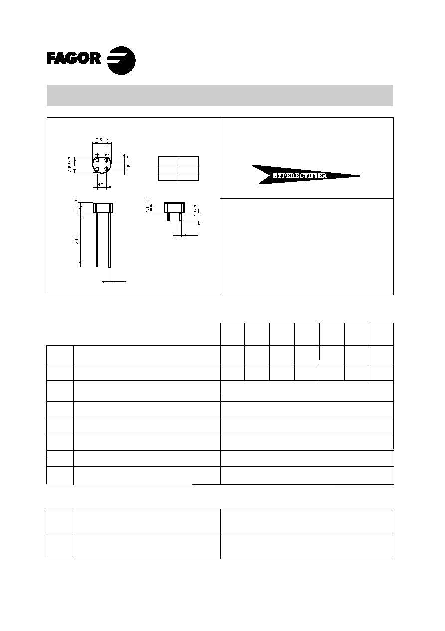
∑ Case: Epoxy encapsulation
∑ Terminals: Radial leads
∑ Ideal for P.C.B.
Lead and polarity identifications
Voltage
50 to 1000 V.
Current
1.5 A
Dimensions in mm.
W
01F
100
W005F.......W10F
1.5 Amp. Glass Passivated Bridge Rectifier
Maximum Ratings, according to IEC publication No. 134
Peak recurrent reverse voltage (V)
Forward current at Tamb = 25 ∞C
Recurrent peak forward current
10 ms. peak forward surge current
I
2
t value for fusing (t = 10 ms)
Operating temperature range
Storage temperature range
V
RRM
I
F(AV)
I
FRM
I
FSM
I
2
t
T
j
T
stg
1.5 A
1.2 A
15 A
50 A
12 A
2
sec
≠ 55 to + 150 ∞C
≠ 55 to + 150 ∞C
Electrical Characteristics at Tamb = 25 ∞C
V
F
Max. forward voltage drop
per element at I
F
= 1 A
I
R
10 µ A
1 V
Max. reverse current per element at V
RRM
W
02F
200
W
04F
400
W
06F
600
W
10F
1000
R load
C load
W
08F
800
W
005F
50
Sufflix
"A"
"B"
L
± 0.5
4
3
ÿ 0.8
± 0.05
ÿ 0.8
± 0.05
Jan - 00
70
Maximum RMS voltage (V)
V
RMS
140
280
420
700
560
35
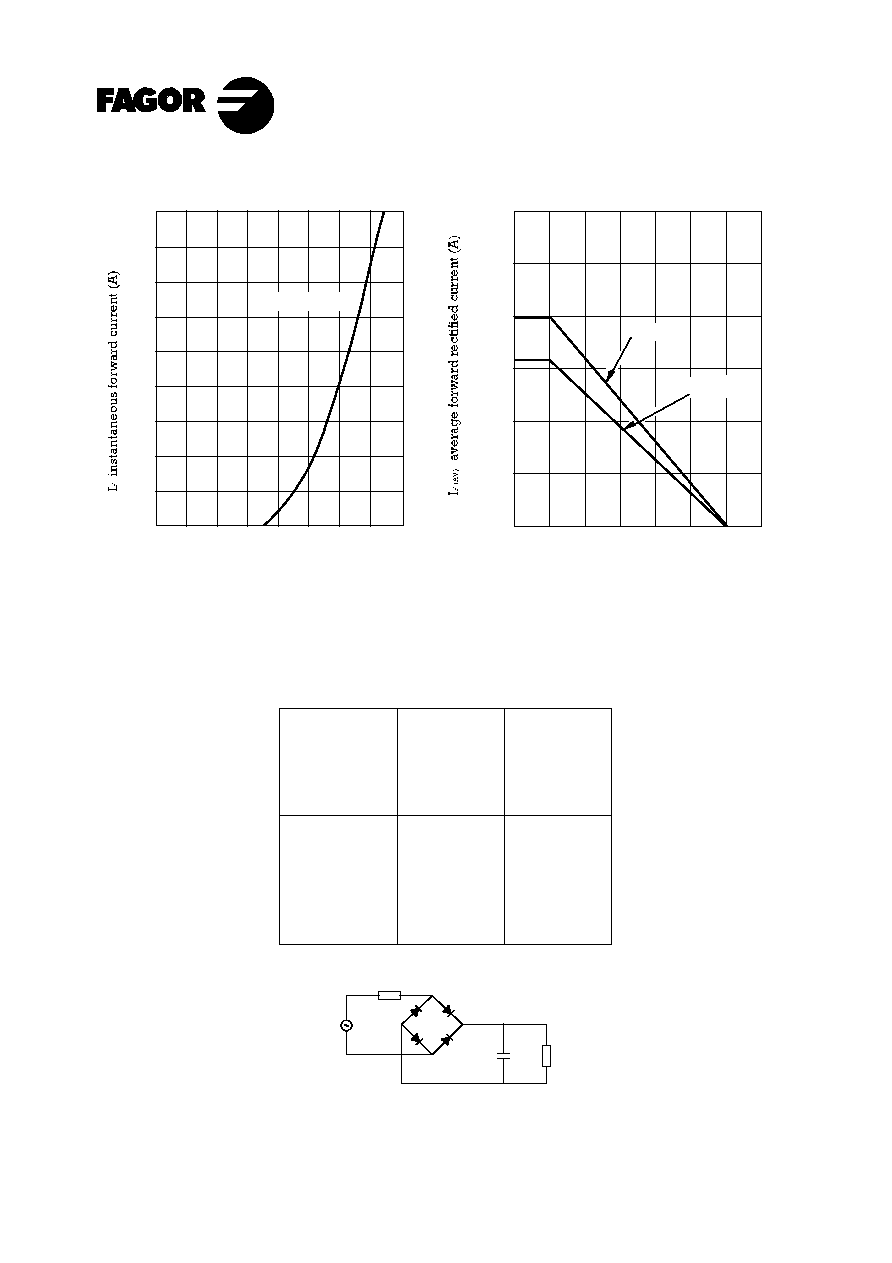
Tamb, ambient temperature (∞ C)
R-Load
C-Load
Characteristic Curves
Tamb = 25∞ C
V
F '
instantaneous forward voltage (V)
4
6
3
2
1
5
7
8
9
10 mA
0
0.4
0.8
1.2
1.6
0.2
0.6
1
1.4
0
50
100
150 175
25
75
125
3
2.5
2
1.5
1
0.5
0
WF
TYPICAL FORWARD CHARACTERISTIC
FORWARD CURRENT DERATING CURVE
R
l
R
S
V
N
C
L
Recommended
input voltage
V
RMS
40
80
125
250
500
Min. RS
Tol ± 10 %
Ohms
1
2
3
6
14
2500
1000
500
250
150
Tol
Limit values of R
S
and C
L
for adequate protection against
switching transients.
OPERATION WITH CAPACITIVE LOAD
Max. CL
+ 50 %
- 20 %
µ F
Jan - 00