DISCRETE POWER AND SIGNAL
TECHNOLOGIES
Absolute Maximum Ratings*
TA = 25
O
C unless otherwise noted
Sym
Parameter
Value
Units
T
stg
Storage Temperature
-65 to +200
O
C
T
J
Operating Junction Temperature
175
O
C
P
D
Total Power Dissipation at T
A
= 25
O
C
500
mW
Linear Derating Factor from T
A
= 25
O
C
3.33
mW/
O
C
R
OJA
Thermal Resistance Junction-to-Ambient
300
O
C/W
W
iv
Working Inverse Voltage
35
V
I
O
Average Rectified Current
100
mA
I
F
DC Forward Current (I
F
)
300
mA
i
f
Recurrent Peak Forward Current (I
F
)
400
mA
i
F(surge)
Peak Forward Surge Current (I
FSM
) Pulse Width = 1.0 second
1.0
Amp
Pulse Width = 1.0 microsecond
4.0
Amp
*These ratings are limiting values above which the serviceability of any semiconductor device may be impaired
1N4154
Electrical Characteristics
TA = 25
O
C unless otherwise noted
SYM
CHARACTERISTICS
MIN
MAX
UNITS
TEST CONDITIONS
B
V
Breakdown Voltage
35
V
I
R
= 5.0 uA
I
R
Reverse Leakage
100
nA
V
R
= 25 V
100
uA
V
R
= 25 V, T
A
= 150
O
C
V
F
Forward Voltage
1.0
V
I
F
= 30 mA
C
T
Capacitance
4.0
pF
V
R
= 0.0 V, f = 1.0 MHz
T
RR
Reverse Recovery Time
4.0
ns
I
F
= 10 mA V
R
= 6.0 V
I
RR
= 1.0 mA, R
L
= 100 ohms
High Conductance
Fast Diode
� 1997 Fairchild Semiconductor Corporation
Features:
� 500 milliwatt Power Dissipation package.
� Fast Switching Speed,
� Typical capacitance less than 1.0 picofarad.
Ordering:
� 13 inch reel, 50 mm (T50R) & 26 mm (T26R) Tape;
10,000 units per reel.
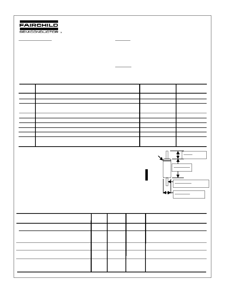
General Description:
The high breakdown voltage, fast switching speed and high
forward conductance of this diode packaged in a DO-35
miniature Glass Axial leaded package makes it desirable also
as a general purpose diode.
CATHODE
BAND
0.200 (5.08)
0.120 (3.05)
0.022 (0.558) Diameter
0.018 (0.458) Typ 20 mils
0.090 (2.28) Diameter
0.060 (1.53)
0.500 Minimum
12.70 Typ 1.000
MARKING
LOGO
1N
41
54
Revision A - September 21, 1998
DO-35 Packaging Information
T50R
TNR
13
10,000
254x79x794
30,000
0.137
2.23
Note/Comments
Packaging Option
Packaging type
Reel Size (inch diameter)
Qty per Reel/Tube/Bag
Int Box Dimension (mm)
Max qty per Box
Weight per unit (gm)
Weight per Reel/Ammo (kg)
Inside Tape Spacing (mm)
52
T50A
Ammo
-
5,000
406x267x184
50,000
0.137
0.800
52
Bulk
Standard
(no flow code)
Bag
-
500
279x133x108
5,000
0.137
-
-
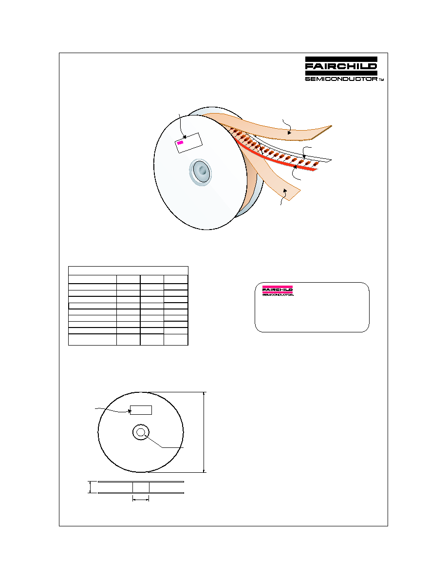
DO-35 Packaging
Configuration: Figure 1.0
Soabar Label sample
P.O. No.
TYPE
IN5225A
MARK
BLK-BRN
REV
A2
PART No.
PKG
EC No.
QTY
10,000
M.O. No.
OX5046F035
Q.C.
DATE
D9903
MFD. UNDER US PAT 3.025.589 & OTHER US PATS & APPLICATIONS
Kraft Paper Wound
Between Layers
Corrugated Outer Liner
Red/Blue (Cathode)
White (Anode)
Soabar Label
DO-35 Packaging
Information Table: Figure 2.0
T50R
TNR Options
REEL DIMENSIONS
ITEM DESCRIPTION
SYMBOL
MINIMUM
MAXIMUM
Reel Diameter
D1
10.375
10.625
Arbor Hole Diameter (Standard)
D2
1.245
1.255
Core Diameter
D3
3.190
3.310
Flange to Flange Inner Width
W1
3.400
Note: All Dimensions are in inches
D1
D3
W1
D2
DO-35 Reel Dimensions:
Figure 3.0
Soabar Label
DO-35 Tape and Reel Data
September 1999, Rev. A

DO-35 Tape and Ammo Data
September 1999, Rev. A
TAPING DIMENSIONS
INCH
MM
MILS
NOTES
A
2.520
64.00
2519
Overall width
+0.066/
+1.69/
+66.5/
-0.027
-0.69
-27.0
B
2.047
�
0.027
52
�
0.69
2047
�
27
Inside Tape Spacing
C
0.200
�
0.0157
5.08
�
0.40
200
�
15.7
Component Pitch
D
0.047(max)
1.2(max)
47(max)
Component Misalignment
E
0.022(max)
0.55(max)
22(max)
Tape Mismatch
F
0.027(max)
�
0.69
�
27
Units in line w/ one another
G
0.126(min)
3.2(min)
126(min)
Lead amount between tapes
H
0
0
0
Lead amount beyond tapes
L1-L2
�
0.027
�
0.69
�
27
Delta between two leads
254mm x 79mm x 79mm
Intermediate Container (5,000 cap)
T50A Option
DO-35 A mmo Packing
Configuration: Figure 4.0
A
F
C
D
L2
L1
E
B
G
H
DO-35 Bulk Packing
Configuration: Figure 6.0
133mm x 95mm
Anti-static bag (500/bag)
Im
102mm x 76mm x 127mm
mediate Box (1,000 cap)
DO-35 Taping
Dimension: Figure 5.0
Soabar Label
(on top of box)

DISCRETE POWER AND SIGNAL
TECHNOLOGIES
DO-35 PACKAGE
Fairchild Semiconductor's Criteria
11-MAR-97
GLASS SLEEVE
0.150 (3.810)
0.140 (3.556)
0.021 (0.533) Diameter
0.019 (0.483)
0.074 (1.880) Diameter
0.068 (1.727)
NOTE 1:
LEAD DIAMETER NOT CONTROLLED IN
THIS ZONE TO ALLOW FOR FLASH, LEAD
FINISH BUILD-UP, & MINOR
IRREGULARITIES OTHER THAN SLUGS.
0.050 (1.270)
Maximum
SEE NOTE 1 BELOW
1.105 (28.067)
1.081 (27.457)
LEADS: COPPER CLAD STEEL
TYPICAL 20 Mils
LEADS TIN DIPPED
(60% S
N
40% P
B)
STUDS: DUMET (ALLOY 42)
STANDARD DIGITAL MARKING CRITERIA
MAXIMUM CHARACTERS PER LINE: 3 MAXIMUM NUMBER OF LINES: 4
LOGO AND CHARACTERS M & W COUNT AS 2 CHARACTERS EACH
Package Weight
0.14 grams
CATHODE BAND
TRADEMARKS
ACExTM
CoolFETTM
CROSSVOLTTM
E
2
CMOS
TM
FACTTM
FACT Quiet SeriesTM
FAST
�
FASTrTM
GTOTM
HiSeCTM
The following are registered and unregistered trademarks Fairchild Semiconductor owns or is authorized to use and is
not intended to be an exhaustive list of all such trademarks.
LIFE SUPPORT POLICY
FAIRCHILD'S PRODUCTS ARE NOT AUTHORIZED FOR USE AS CRITICAL COMPONENTS IN LIFE SUPPORT
DEVICES OR SYSTEMS WITHOUT THE EXPRESS WRITTEN APPROVAL OF FAIRCHILD SEMICONDUCTOR CORPORATION.
As used herein:
1. Life support devices or systems are devices or
systems which, (a) are intended for surgical implant into
the body, or (b) support or sustain life, or (c) whose
failure to perform when properly used in accordance
with instructions for use provided in the labeling, can be
reasonably expected to result in significant injury to the
user.
2. A critical component is any component of a life
support device or system whose failure to perform can
be reasonably expected to cause the failure of the life
support device or system, or to affect its safety or
effectiveness.
PRODUCT STATUS DEFINITIONS
Definition of Terms
Datasheet Identification
Product Status
Definition
Advance Information
Preliminary
No Identification Needed
Obsolete
This datasheet contains the design specifications for
product development. Specifications may change in
any manner without notice.
This datasheet contains preliminary data, and
supplementary data will be published at a later date.
Fairchild Semiconductor reserves the right to make
changes at any time without notice in order to improve
design.
This datasheet contains final specifications. Fairchild
Semiconductor reserves the right to make changes at
any time without notice in order to improve design.
This datasheet contains specifications on a product
that has been discontinued by Fairchild semiconductor.
The datasheet is printed for reference information only.
Formative or
In Design
First Production
Full Production
Not In Production
DISCLAIMER
FAIRCHILD SEMICONDUCTOR RESERVES THE RIGHT TO MAKE CHANGES WITHOUT FURTHER
NOTICE TO ANY PRODUCTS HEREIN TO IMPROVE RELIABILITY, FUNCTION OR DESIGN. FAIRCHILD
DOES NOT ASSUME ANY LIABILITY ARISING OUT OF THE APPLICATION OR USE OF ANY PRODUCT
OR CIRCUIT DESCRIBED HEREIN; NEITHER DOES IT CONVEY ANY LICENSE UNDER ITS PATENT
RIGHTS, NOR THE RIGHTS OF OTHERS.
SyncFETTM
TinyLogicTM
UHCTM
VCXTM
ISOPLANARTM
MICROWIRETM
POPTM
PowerTrench
QFETTM
QSTM
Quiet SeriesTM
SuperSOTTM-3
SuperSOTTM-6
SuperSOTTM-8
Rev. D