 | –≠–ª–µ–∫—Ç—Ä–æ–Ω–Ω—ã–π –∫–æ–º–ø–æ–Ω–µ–Ω—Ç: 74F1056 | –°–∫–∞—á–∞—Ç—å:  PDF PDF  ZIP ZIP |

© 1999 Fairchild Semiconductor Corporation
DS011655
www.fairchildsemi.com
December 1993
Revised August 1999
7
4F1056 8-Bi
t Schott
ky Barri
er Diod
e
Arr
a
y
74F1056
8-Bit Schottky Barrier Diode Array
General Description
The 74F1056 is an 8-bit Schottky barrier diode array
designed to be employed as termination on the inputs to
memory bus lines or CLOCK lines. This device is designed
to suppress negative transients caused by line reflections,
switching noise and crosstalk.
Features
s
8-Bit array structure designed to suppress negative
transients
s
Guaranteed ESD protection (HBM) in excess of 4 kV
s
Common anode shared by all eight diodes
s
Broadside pinout for ease of bus routing
Ordering Code:
Devices also available in Tape and Reel. Specify by appending the suffix letter "X" to the ordering code.
Connection Diagram
Schematic Diagram
Order Number
Package Number
Package Description
74F1056SC
M16A
16-Lead Small Outline Integrated Circuit (SOIC), JEDEC MS-012, 0.150 Narrow

www.fairchildsemi.com
2
74F1056
Absolute Maximum Ratings
(Note 1)
Note 1: Absolute maximum ratings are valued beyond which the device
may be damaged or have its useful life impaired. Functional operation
under these conditions is not implied.
Note 2: These values apply for the t
w
100
µ
s, duty cycle
20%.
DC Electrical Characteristics
Over recommended operating free air temperature range, unless otherwise noted
SINGLE DIODE OPERATION (Note 3)
Note 3: These tests apply to separate diode operation, diodes not under test are open-circuit.
MULTIPLE DIODE OPERATION
Note 4: I
CR
is measured under the following conditions:
One diode static, all others switching
Switching diodes: t
W
=
100
µ
s; Static diode: V
IN
=
6V
Duty cycle
=
20%, I
f
=
200 mA
The static diode input current is the internal crosstalk current I
CR
.
AC Electrical Characteristics
T
A
=
25
∞
C
Storage Temperature
-
65
∞
C to
+
150
∞
C
Operating Free-Air Temperature
0
∞
C to 70
∞
C
Steady State Reverse Voltage, (V
R
)
7.0V
Continuous Total Power Dissipation at or below
25
∞
C Free-Air Temperature, (P
D
)
750 mW
Continuous Forward Current, (I
f
)
Any Output Pin to GND
50 mA
Total Through All GND Pins
170 mA
Repetitive Peak Forward Current, lfp (Note 2)
Any Output Pin to GND
300 mA
Total Through All GND Pins
1.2A
ESD (HBM)
4 kV
Symbol
Parameter
Min
Typ
Max
Units
Conditions
V
BR
Reverse Breakdown Voltage
7.0
V
I
R
=
10
µ
A
I
R
Static Reverse Current
10
µ
A
V
R
=
7V
V
F
Static Forward Voltage
-
0.65
-
0.85
V
I
F
=
-
16 mA
-
0.8
-
1.0
I
F
=
-
50 mA
C
T
Total Capacitance
5
10
pF
V
I
=
0V, f
=
1 MHz
4
8
V
I
=
2V, f
=
1 MHz
Symbol
Parameter
Min
Typ
Max
Units
Conditions
I
CR
Internal Crosstalk Current
0.2
2
mA
Total GND current
=
1.2A (Note 4)
Symbol
Parameter
Min
Typ
Max
Units
Conditions
Figure
Number
V
FR
Forward Recovery Voltage
1.25
V
I
F
=
300 mA
Figure 1
T
RR
Reverse Recovery Time
5.0
ns
I
F
=
10 mA, I
R
=
1 mA
Figure 2
R
L
=
100

3
www.fairchildsemi.com
7
4F1056
AC Loading and Waveforms
t
r
=
20 ns, Z
O
=
50
, freq
=
500 Hz
FIGURE 1. Forward Recovery Voltage
t
f
=
0.5 ns, Z
O
=
50
, t
W
=
50 ns, duty cycle
=
0.01
R
L
=
100
(Note )
Monitored by Oscilloscope having the following characteristics: t
r
350 ps, R
I
=
50
, C
I
=
5 pF.
FIGURE 2. Reverse Recovery Time
www.fairchildsemi.com
4
74F105
6 8-
Bit
Schot
tk
y Bar
r
ie
r
D
i
ode
Array
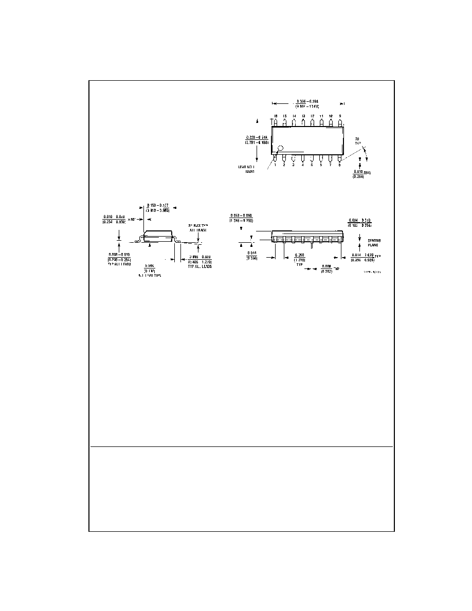
Physical Dimensions
inches (millimeters) unless otherwise noted
16-Lead Small Outline Integrated Circuit (SOIC), JEDEC MS-012, 0.150 Narrow
Package Number M16A
Fairchild does not assume any responsibility for use of any circuitry described, no circuit patent licenses are implied and
Fairchild reserves the right at any time without notice to change said circuitry and specifications.
LIFE SUPPORT POLICY
FAIRCHILD'S PRODUCTS ARE NOT AUTHORIZED FOR USE AS CRITICAL COMPONENTS IN LIFE SUPPORT
DEVICES OR SYSTEMS WITHOUT THE EXPRESS WRITTEN APPROVAL OF THE PRESIDENT OF FAIRCHILD
SEMICONDUCTOR CORPORATION. As used herein:
1. Life support devices or systems are devices or systems
which, (a) are intended for surgical implant into the
body, or (b) support or sustain life, and (c) whose failure
to perform when properly used in accordance with
instructions for use provided in the labeling, can be rea-
sonably expected to result in a significant injury to the
user.
2. A critical component in any component of a life support
device or system whose failure to perform can be rea-
sonably expected to cause the failure of the life support
device or system, or to affect its safety or effectiveness.
www.fairchildsemi.com