
© 2005 Fairchild Semiconductor Corporation
ds500168
www.fairchildsemi.com
March 2000
Revised June 2005
7
4
VC
X16
3245 L
o
w
V
o
lt
age
16-
Bit
Dual
Sup
p
ly
T
r
ansl
at
ing
T
r
ans
ceive
r wi
th
3-ST
A
T
E Out
put
s
74VCX163245
Low Voltage 16-Bit Dual Supply Translating Transceiver
with 3-STATE Outputs
General Description
The VCX163245 is a dual supply, 16-bit translating trans-
ceiver that is designed for 2 way asynchronous communi-
cation between busses at different supply voltages by
providing true signal translation. The supply rails consist of
V
CCA
, which is a higher potential rail operating at 2.3V to
3.6V and V
CCB
, which is the lower potential rail operating at
1.65V to 2.7V. (V
CCB
must be less than or equal to V
CCA
for proper device operation). This dual supply design
allows for translation from 1.8V to 2.5V busses to busses at
a higher potential, up to 3.3V.
The Transmit/Receive (T/R) input determines the direction
of data flow. Transmit (active-HIGH) enables data from A
Ports to B Ports; Receive (active-LOW) enables data from
B Ports to A Ports. The Output Enable (OE) input, when
HIGH, disables both A and B Ports by placing them in a
High-Z condition. The A Port interfaces with the higher volt-
age bus (2.7V to 3.3V); The B Port interfaces with the lower
voltage bus (1.8V to 2.5V). Also the VCX163245 is
designed so that the control pins (T/R
n
, OE
n
) are supplied
by V
CCB
.
The 74VCX163245 is suitable for mixed voltage applica-
tions such as notebook computers using a 1.8V CPU and
3.3V peripheral components. It is fabricated with an
Advanced CMOS technology to achieve high speed opera-
tion while maintaining low CMOS power dissipation.
Features
s
Bidirectional interface between busses ranging from
1.65V to 3.6V
s
Supports Live Insertion and Withdrawal (Note 1)
s
Static Drive (I
OH
/I
OL
)
r
24 mA @ 3.0V V
CC
r
18 mA @ 2.3V V
CC
r
6 mA @ 1.65V V
CC
s
Uses patented Quiet Series
•
noise/EMI reduction
circuitry
s
Functionally compatible with 74 series 16245
s
Latchup performance exceeds 300 mA
s
ESD performance:
Human Body Model
!
2000V
Machine model
!
200V
s
Also packaged in plastic Fine-Pitch Ball Grid Array
(FBGA)
Note 1: To ensure the high impedance state during power up or power
down, OE
n
should be tied to V
CCB
through a pull up resistor. The minimum
value of the resistor is determined by the current sourcing capability of the
driver.
Ordering Code:
Note 2: Ordering code "G" indicates Trays.
Note 3: Device also available in Tape and Reel. Specify by appending the suffix letter "X" to the ordering code.
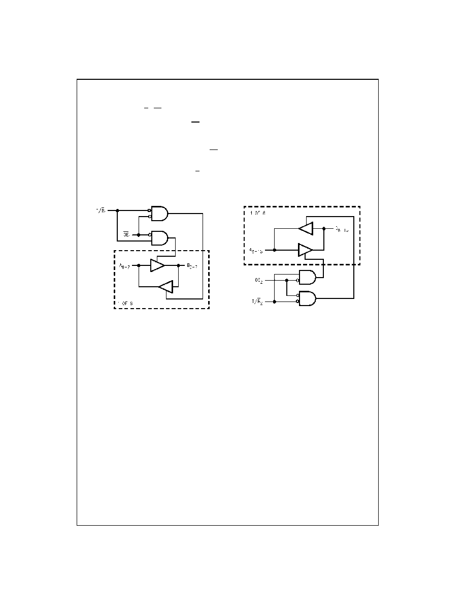
Logic Diagram
Quiet Series
•
is a trademark of Fairchild Semiconductor Corporation.
Order Number
Package Number
Package Description
74VCX163245G
(Note 2)(Note 3)
BGA54A
54-Ball Fine-Pitch Ball Grid Array (FBGA), JEDEC MO-205, 5.5mm Wide
74VCX163245MTD
(Note 3)
MTD48
48-Lead Thin Shrink Small Outline Package (TSSOP), JEDEC MO-153, 6.1mm Wide
www.fairchildsemi.com
2
74VCX163245
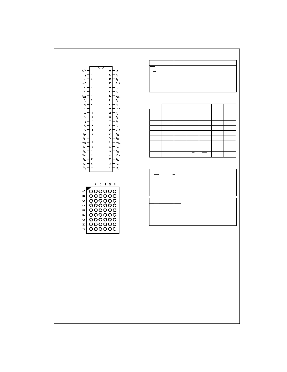
Connection Diagrams
Pin Assignment for TSSOP
Pin Assignment for FBGA
(Top Thru View)
Pin Descriptions
FBGA Pin Assignments
Truth Tables
H
HIGH Voltage Level
L
LOW Voltage Level
X
Immaterial (HIGH or LOW, inputs may not float)
Z
High Impedance
Pin Names
Description
OE
n
Output Enable Input (Active LOW)
T/R
n
Transmit/Receive Input
A
0
≠A
15
Side A Inputs or 3-STATE Outputs
B
0
≠B
15
Side B Inputs or 3-STATE Outputs
NC
No Connect
1
2
3
4
5
6
A
B
0
NC
T/R
1
OE
1
NC
A
0
B
B
2
B
1
NC
NC
A
1
A
2
C
B
4
B
3
V
CCB
V
CCA
A
3
A
4
D
B
6
B
5
GND
GND
A
5
A
6
E
B
8
B
7
GND
GND
A
7
A
8
F
B
10
B
9
GND
GND
A
9
A
10
G
B
12
B
11
V
CCB
V
CCA
A
11
A
12
H
B
14
B
13
NC
NC
A
13
A
14
J
B
15
NC
T/R
2
OE
2
NC
A
15
Inputs
Outputs
OE
1
T/R
1
L
L
Bus B
0
≠B
7
Data to Bus A
0
≠A
7
L
H
Bus A
0
≠A
7
Data to Bus B
0
≠B
7
H
X
HIGH Z State on A
0
≠A
7
, B
0
≠B
7
Inputs
Outputs
OE
2
T/R
2
L
L
Bus B
8
≠B
15
Data to Bus A
8
≠A
15
L
H
Bus A
8
≠A
15
Data to Bus B
8
≠B
15
H
X
HIGH-Z State on A
8
≠A
15
, B
8
≠B
15
3
www.fairchildsemi.com
7
4
VC
X16
3245
VCX163245 Translator Power Up Sequence Recommendations
To guard against power up problems, some simple guide-
lines need to be adhered to. The VCX163245 is designed
so that the control pins (T/R
n
, OE
n
) are supplied by V
CCB
.
Therefore the first recommendation is to begin by powering
up the control side of the device, V
CCB
. The OE
n
control
pins should be ramped with or ahead of V
CCB
, this will
guard against bus contentions and oscillations as all A Port
and B Port outputs will be disabled. To ensure the high
impedance state during power up or power down, OE
n
should be tied to V
CCB
through a pull up resistor. The mini-
mum value of the resistor is determined by the current
sourcing capability of the driver. Second, the T/R
n
control
pins should be placed at logic LOW (0V) level, this will
ensure that the B-side bus pins are configured as inputs to
help guard against bus contention and oscillations. B-side
Data Inputs should be driven to a valid logic level (0V or
V
CCB
), this will prevent excessive current draw and oscilla-
tions. V
CCA
can then be powered up after V
CCB
, however
V
CCA
must be greater than or equal to V
CCB
to ensure
proper device operation. Upon completion of these steps
the device can then be configured for the users desired
operation. Following these steps will help to prevent possi-
ble damage to the translator device as well as other system
components.
Logic Diagrams
Please note that these diagrams are provided only for the understanding of logic operations and should not be used to estimate propagation delays.

www.fairchildsemi.com
4
74VCX163245
Absolute Maximum Ratings
(Note 4)
Recommended Operating
Conditions
(Note 6)
Note 4: The "Absolute Maximum Ratings" are those values beyond which
the safety of the device cannot be guaranteed. The device should not be
operated at these limits. The parametric values defined in the Electrical
Characteristics tables are not guaranteed at the absolute maximum ratings.
The "Recommended Operating Conditions" table will define the conditions
for actual device operation.
Note 5: I
O
Absolute Maximum Rating must be observed.
Note 6: Unused inputs or I/O pins must be held HIGH or LOW. They may
not float.
Note 7: Operation requires: V
CCB
d
V
CCA
DC Electrical Characteristics (1.65V
V
CCB
d
1.95V, 2.3V
V
CCA
d
2.7V)
Supply Voltage
V
CCA
0.5V to
4.6V
V
CCB
0.5V to V
CCA
DC Input Voltage (V
I
)
0.5V to
4.6V
DC Output Voltage (V
I/O
)
Outputs 3-STATE
0.5V to
4.6V
Outputs Active (Note 5)
A
n
0.5V to V
CCA
0.5V
B
n
0.5V to V
CCB
0.5V
DC Input Diode Current (I
IK
)
V
I
0V
50 mA
DC Output Diode Current (I
OK
)
V
O
0V
50 mA
V
O
!
V
CC
50 mA
DC Output Source/Sink Current
(I
OH
/I
OL
)
r
50 mA
DC V
CC
or Ground Current
r
100 mA
Supply Pin (I
CC
or Ground)
Storage Temperature (T
STG
)
65
q
C to
150
q
C
Power Supply (Note 7)
V
CCA
2.3V to 3.6V
V
CCB
1.65V to 2.7V
Input Voltage (V
I
) @ OE, T/R
0V to V
CCB
Input/Output Voltage (V
I/O
)
A
n
0V to V
CCA
B
n
0V to V
CCB
Output Current in I
OH
/I
OL
V
CCA
3.0V to 3.6V
r
24 mA
V
CCA
2.3V to 2.7V
r
18 mA
V
CCB
2.3V to 2.7V
r
18 mA
V
CCB
1.65V to 1.95V
r
6 mA
Free Air Operating Temperature (T
A
40
q
C to
85
q
C
Minimum Input Edge Rate (
'
t/
'
V)
V
IN
0.8V to 2.0V, V
CC
3.0V
10 ns/V
Symbol
Parameter
Conditions
V
CCB
V
CCA
Min
Max
Units
(V)
(V)
V
IHA
HIGH Level Input Voltage A
n
1.65≠1.95
2.3≠2.7
1.6
V
V
IHB
B
n
, T/R, OE
1.65≠1.95
2.3≠2.7
0.65 x V
CCB
V
V
ILA
LOW Level Input Voltage
A
n
1.65≠1.95
2.3≠2.7
0.7
V
V
ILB
B
n
, T/R, OE
1.65≠1.95
2.3≠2.7
0.35 x V
CCB
V
V
OHA
HIGH Level Output Voltage
I
OH
100
P
A
1.65≠1.95
2.3≠2.7
V
CCA
≠0.2
V
I
OH
18 mA
1.65
2.3≠2.7
1.7
V
OHB
HIGH Level Output Voltage
I
OH
100
P
A
1.65≠1.95
2.3≠2.7
V
CCB
≠0.2
V
I
OH
6 mA
1.65≠1.95
2.3
1.25
V
OLA
Low Level Output Voltage
I
OL
100
P
A
1.65≠1.95
2.3≠2.7
0.2
V
I
OL
18 mA
1.65
2.3≠2.7
0.6
V
OLB
Low Level Output Voltage
I
OL
100
P
A
1.65≠1.95
2.3≠2.7
0.2
V
I
OL
6 mA
1.65≠1.95
2.3
0.3
I
I
Input Leakage Current @ OE, T/R
0V
d
V
I
d
3.6V
1.65≠1.95
2.3≠2.7
r
5.0
P
A
I
OZ
3-STATE Output Leakage
0V
d
V
O
d
3.6V
1.65≠1.95
2.3≠2.7
r
10
P
A
OE
V
CCB
V
I
V
IH
or V
IL
I
OFF
Power Off Leakage Current
0
d
(V
I
, V
O
)
d
3.6V
0
0
10
P
A
I
CCA
/I
CCB
Quiescent Supply Current,
A
n
V
CCA
or GND
1.65≠1.95
2.3≠2.7
20
P
A
per supply, V
CCA
/ V
CCB
B
n
, OE, & T/R
V
CCB
or GND
V
CCA
d
An
d
3.6V
1.65≠1.95
2.3≠2.7
r
20
P
A
V
CCB
d
B
n
, OE, T/R
d
3.6V
'
I
CC
Increase in I
CC
per Input, B
n
, T/R, OE
V
I
V
CCB
≠ 0.6V
1.65≠1.95
2.3≠2.7
750
P
A
Increase in I
CC
per Input, A
n
V
I
V
CCA
≠ 0.6V
1.65≠1.95
2.3≠2.7
750
P
A

5
www.fairchildsemi.com
7
4
VC
X16
3245
DC Electrical Characteristics (1.65V
V
CCB
d
1.95V, 3.0V
V
CCA
d
3.6V)
DC Electrical Characteristics (2.3V
V
CCB
d
2.7V, 3.0V
d
V
CCA
d
3.6V)
Symbol
Parameter
Conditions
V
CCB
V
CCA
Min
Max
Units
(V)
(V)
V
IHA
HIGH Level Input Voltage A
n
1.65≠1.95
3.0≠3.6
2.0
V
V
IHB
B
n
, T/R, OE
1.65≠1.95
3.0≠3.6
0.65 x V
CCB
V
V
ILA
LOW Level Input Voltage
A
n
1.65≠1.95
3.0≠3.6
0.8
V
V
ILB
B
n
, T/R, OE
1.65≠1.95
3.0≠3.6
0.35 x V
CCB
V
V
OHA
HIGH Level Output Voltage
I
OH
100
P
A
1.65≠1.95
3.0≠3.6
V
CCA
≠0.2
V
I
OH
24 mA
1.65
3.0≠3.6
2.2
V
OHB
HIGH Level Output Voltage
I
OH
100
P
A
1.65≠1.95
3.0≠3.6
V
CCA
≠0.2
V
I
OH
6 mA
1.65≠1.95
3.0
1.25
V
OLA
LOW Level Output Voltage
I
OL
100
P
A
1.65≠1.95
3.0≠3.6
0.2
V
I
OL
24 mA
1.65
3.0≠3.6
0.55
V
OLB
LOW Level Output Voltage
I
OL
100
P
A
1.65≠1.95
3.0≠3.6
0.2
V
I
OL
6 mA
1.65≠1.95
3.0
0.3
I
I
Input Leakage Current @ OE, T/R
0V
d
V
I
d
3.6V
1.65≠1.95
3.0≠3.6
r
5.0
P
A
I
OZ
3-STATE Output Leakage
0V
d
V
O
d
3.6V
1.65≠1.95
3.0≠3.6
r
10
P
A
OE*
V
CCB
V
I
V
IH
or V
IL
I
OFF
Power OFF Leakage Current
0
d
(V
I
, V
O
)
d
3.6V
0
0
10
P
A
I
CCA
/I
CCB
Quiescent Supply Current,
A
n
V
CCA
or GND
1.65≠1.95
3.0≠3.6
20
P
A
per supply, V
CCA
/V
CCB
B
n
, OE, & T/R
V
CCB
or GND
V
CCA
d
A
n
d
3.6V
1.65≠1.95
3.0≠3.6
r
20
P
A
V
CCB
d
B
n
, OE, T/R
d
3.6V
'
I
CC
Increase in I
CC
per Input, B
n
, T/R, OE
V
I
V
CCB
0.6V
1.65≠1.95
3.0≠3.6
750
P
A
Increase in I
CC
per Input, A
n
V
I
V
CCA
0.6V
1.65≠1.95
3.0≠3.6
750
P
A
Symbol
Parameter
Conditions
V
CCB
V
CCA
Min
Max
Units
(V)
(V)
V
IHA
HIGH Level Input Voltage A
n
2.3≠2.7
3.0≠3.6
2.0
V
V
IHB
B
n
, T/R, OE
2.3≠2.7
3.0≠3.6
1.6
V
V
ILA
LOW Level Input Voltage
A
n
2.3≠2.7
3.0≠3.6
0.8
V
V
ILB
B
n
, T/R, OE
2.3≠2.7
3.0≠3.6
0.7
V
V
OHA
HIGH Level Output Voltage
I
OH
100
P
A
2.3≠2.7
3.0≠3.6
V
CCA
≠0.2
V
I
OH
24 mA
2.3
3.0≠3.6
2.2
V
OHB
HIGH Level Output Voltage
I
OH
100
P
A
2.3≠2.7
3.0≠3.6
V
CCB
≠0.2
V
I
OH
18 mA
2.3≠2.7
3.0
1.7
V
OLA
LOW Level Output Voltage
I
OL
100
P
A
2.3≠2.7
3.0≠3.6
0.2
V
I
OL
24 mA
2.3
3.0≠3.6
0.55
V
OLB
LOW Level Output Voltage
I
OL
100
P
A
2.3≠2.7
3.0≠3.6
0.2
V
I
OL
18 mA
2.3≠2.7
3.0
0.6
I
I
Input Leakage Current @ OE, T/R
0V
d
V
I
d
3.6V
2.3≠2.7
3.0≠3.6
r
5.0
P
A
I
OZ
3-STATE Output Leakage @ A
n
0V
d
V
O
d
3.6V
2.3≠2.7
3.0≠3.6
r
10
P
A
OE
V
CCA
V
I
V
IH
or V
IL
I
OFF
Power OFF Leakage Current
0
d
(V
I
, V
O
)
d
3.6V
0
0
10
P
A
I
CCA
/I
CCB
Quiescent Supply Current,
A
n
V
CCA
or GND
2.3≠2.7
3.0≠3.6
20
P
A
per supply, V
CCA
/V
CCB
B
n
, OE, & T/R
V
CCB
or GND
V
CCA
d
A
n
d
3.6V
2.3≠2.7
3.0≠3.6
r
20
P
A
V
CCB
d
B
n
, OE, T/R
d
3.6V
'
I
CC
Increase in I
CC
per Input, B
n
, T/R, OE
V
I
V
CCB
0.6V
2.3≠2.7
3.0≠3.6
750
P
A
Increase in I
CC
per Input, A
n
V
I
V
CCA
0.6V
2.3≠2.7
3.0≠3.6
750
P
A