©2002 Fairchild Semiconductor Corporation
1
www.fairchildsemi.com
November 2002
A
CE8001 Pr
oduct F
a
mil
y
Arithmetic Contr
oller Engine (A
CExTM) f
or Lo
w P
o
wer Applications
ACE8001 Product Family Rev. B.2
ACE8001 Product Family
Arithmetic Controller Engine (ACExTM)
for Low Power Applications
General Description
The ACE8001 is a member of the ACEx (Arithmetic Controller
Engine) family of microcontrollers. It is a dedicated programma-
ble monolithic integrated circuit for applications requiring high
performance, low power, and small size. It is a fully static part
fabricated using CMOS technology.
The ACE8001 product family has an 8-bit core processor, 64
bytes of RAM, 64 bytes of data EEPROM and 1K bytes of code
EEPROM. Its on-chip peripherals include a programmable 8-bit
timer with PWM output, watch-dog/idle timer, and programma-
ble undervoltage detection circuitry. The on-chip clock and reset
functions reduce the number of required external components.
The ACE8001 product family is available in 8-pin SOIC and
TSSOP packages.
Features
s
Arithmetic Controller Engine
s
1K bytes on-board code EEPROM
s
64 bytes data EEPROM
s
Fast Startup (<10µS)
s
64 bytes RAM
s
Watchdog
s
Multi-input wake-up 3 I/O pins
s
8-bit Timer1 with PWM output
s
On-chip oscillator
-- No external components
-- 1µs instruction cycle time
s
On-chip Power-on Reset
-- External Reset pin option (ACE8000)
s
Brown-out Reset
s
Programmable read and write disable functions
s
Memory mapped I/O
s
Multilevel Low Voltage Detection
s
Fully static CMOS
-- Low power HALT mode (100nA @ 3.3V)
-- Power saving IDLE mode
s
Single supply operaton
-- 2.2 - 5.5V
s
Software selectable I/O options
-- Push-pull outputs with tri-state option
-- Weak pull-up or high impedance inputs
s
40 years data retention
s
1,000,000 writes
s
8-pin SOIC and TSSOP packages.
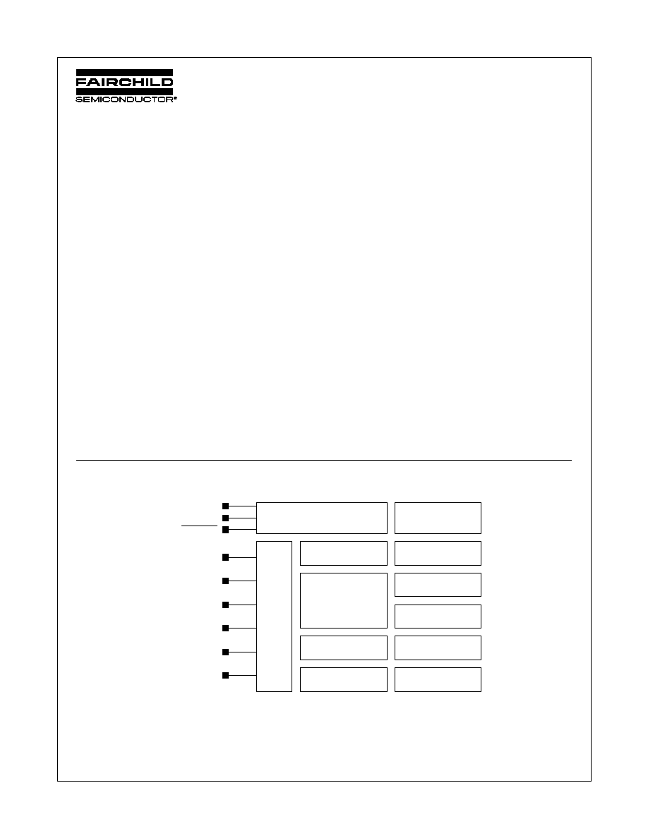
Block and Connection Diagram
Power-on Reset
Brown-out Reset
ACE1001 core
(4 interrupt
sources
and vectors)
Programming Interface
1K bytes of Code
EEPROM
64 bytes of Data
EEPROM
64 bytes of RAM
12-bit Timer0 with
Watchdog Timer
8-bit PWM Timer1
HALT & IDLE Power
Saving Modes
GPORT
general
purpose
I/O with
multi-
input
wakeup
on 3
inputs
Internal Oscillator
VCC
1
GND
1
RESET
(CKO) G0
(CKI) G1
(T1) G2
(MIW) G4
(MIW) G5
(MIW) G3
2
1. 100nf decoupling capacitor recommended.
2. Input only
2
www.fairchildsemi.com
ACE8001 Product Family Rev. B.2
A
CE8001 Pr
oduct F
a
mil
y
Arithmetic Contr
oller Engine (A
CExTM) f
or Lo
w P
o
wer Applications
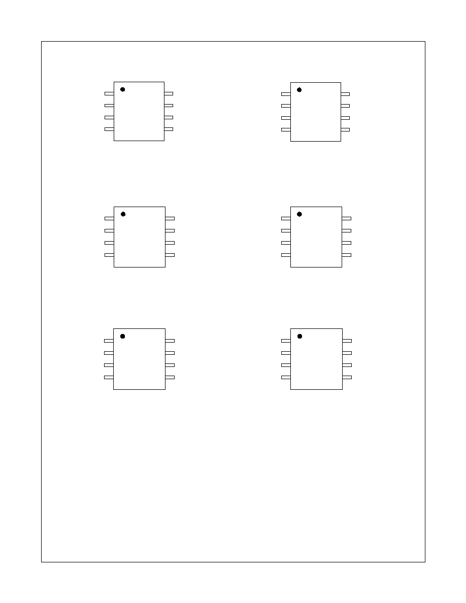
Figure 1: ACE8001 SOIC 8-Pin Device Pinout
(a) Normal Operation
(b) Programming Mode
Figure 2: ACE8000 SOIC 8-Pin Reset Option
(a) Normal Operation
(b) Programming Mode
Figure 3: ACE8001 TSSOP 8-Pin Device Pinout
(a) Normal Operation
(b) Programming Mode
(MIW) G3
VCC
GND
G2 (T1)
G1 (CKI)
1
2
3
4
5
6
7
8
(MIW) G4
(CKO) G0
(MIW) G5
LOAD
VCC
GND
SFT_OUT
CKI
1
2
3
4
5
6
7
8
SFT_IN
NC/VCC
NC
(MIW) G3
VCC
GND
G2 (T1)
G1 (CKI)
1
2
3
4
5
6
7
8
(MIW) G4
(CKO) G0
Reset
LOAD
VCC
GND
SFT_OUT
CKI
1
2
3
4
5
6
7
8
SFT_IN
NC
NC
(MIW) G3
VCC
GND
G2 (T1)
G1 (CKI)
1
2
3
4
5
6
7
8
(MIW) G4
G0 (CKO)
(MIW) G5
LOAD
VCC
GND
SFT_OUT
CKI
1
2
3
4
5
6
7
8
SFT_IN
NC
NC/VCC

A
CE8001 Pr
oduct F
a
mil
y
Arithmetic Contr
oller Engine (A
CExTM) f
or Lo
w P
o
wer Applications
3
www.fairchildsemi.com
ACE8001 Product Family Rev. B.2
2.0 Electrical Characteristics
Absolute Maximum Ratings
Ambient Storage Temperature
-65∞C to +150∞C
Input Voltage not including G3
-0.3V to V
CC
+0.3V
G3 Input Voltage
0.3V to 13V
Lead Temperature (10s max)
+300∞C
Electrostatic Discharge on all pins
2000V min
Operating Conditions
Relative Humidity (non-condensing)
95%
EEPROM write limits
See DC Electrical
Characteristics
Device
Operating Voltage
Operating Temperature
ACE8001
2.2 to 5.5V
0∞C to 70∞C
ACE8001E
2.2 to 5.5V
-40∞C to +85∞C
ACE8000
2.2 to 5.5V
0∞C to 70∞C
ACE8000E
2.2 to 5.5V
-40∞C to +85∞C

4
www.fairchildsemi.com
ACE8001 Product Family Rev. B.2
A
CE8001 Pr
oduct F
a
mil
y
Arithmetic Contr
oller Engine (A
CExTM) f
or Lo
w P
o
wer Applications
ACE8001 DC Electrical Characteristics
V
CC
= 2.2 to 5.5V
All measurements valid for ambient operating temperature unless otherwise stated.
3
I
CC
active current is dependent on the program code.
4
Based on a continuous IDLE looping program.
Symbol
Parameter
Conditions
MIN
TYP
MAX
Units
I
CC
3
Supply Current ≠
no data EEPROM write in
progress
-40∞C to +85∞C
2.2V
2.7V
3.3V
5.5V
0.4
0.7
1.2
3.7
1.0
1.2
2.0
6.0
mA
mA
mA
mA
I
CCH
HALT Mode current
3.3V @ -40∞C to +85∞C
100
5000
nA
5.5V @ -40∞C to +85∞C
0.7
25
µA
I
CCL
4
IDLE Mode Current
3.3V
5.5V
120
140
200
350
µA
µA
V
CCW
EEPROM Write Voltage
Code EEPROM in
Programming Mode
4.5
5.0
5.5
V
Data EEPROM in
Operating Mode
2.4
5.5
V
S
VCC
Power Supply Slope
1µs/V
10ms/V
V
IL
Input Low with Schmitt
Trigger Buffer
V
CC
= 2.2 -5.5V
0.2V
CC
V
V
IH
Input High with Schmitt
Trigger Buffer
V
CC
= 2.2V
V
CC
> 2.2V
0.9V
CC
0.8V
CC
V
V
I
IP
Input Pull-up Current
V
CC
=5.5V, V
IN
=0V
30
65
350
µA
I
TL
TRI-STATE Leakage
V
CC
=5.5V
2
200
nA
V
OL
Output Low Voltage
V
CC
= 2.2V ≠ 3.3V
G0, G1, G2, G4
3.0 mA sink
0.2V
CC
V
G5
5.0 mA sink
0.2V
CC
V
Output Low Voltage
V
CC
= 3.3V ≠ 5.5V
G0, G1, G2, G4
5.0 mA sink
0.2V
CC
V
G5
10.0 mA sink
0.2V
CC
V
V
OH
Output High Voltage
V
CC
= 2.2V ≠ 5.5V
G0, G1, G2, G4
0.4 mA source
0.8V
CC
V
G5
0.8 mA source
0.8V
CC
V
Output High Voltage
V
CC
= 3.3V ≠ 5.5V
G0, G1, G2, G4
0.4 mA source
0.8V
CC
V
G5
1.0 mA source
0.8V
CC
V

5
www.fairchildsemi.com
ACE8001 Product Family Rev. B.2
A
CE8001 Pr
oduct F
a
mil
y
Arithmetic Contr
oller Engine (A
CExTM) f
or Lo
w P
o
wer Applications
ACE8001 AC Electrical Characteristics
V
CC
= 2.2 to 5.5V
All measurements valid for ambient operating temperature unless otherwise stated.
5
The maximum permissible frequency is guaranteed by design but not 100% tested.
6
The parameter is guaranteed by design but not 100% tested.
ACE8001 Electrical Characteristics for programming
All data following is valid between 4.5V and 5.5V at ambient temperature. The following characteristics are
guaranteed by design but are not 100% tested. See "EEPROM write time" in the AC Electrical Characteris-
tics for definition of the programming ready time.
ACE8001 Brown-out Reset (BOR) Characteristics
V
CC
= 2.2 to 5.5V
Parameter
Conditions
MIN
TYP
MAX
Units
Instruction cycle time from
internal clock - setpoint
5.0V at +25∞C 0.96
1.0
1.04
µs
Internal clock frequency
variation
2.4V to 5.5V at
constant temperature
10
%
2.4V to 5.5V at
full temperature range
-12
+8
%
Crystal oscillator frequency
(Note 5)
4
MHz
External clock frequency
(Note 5)
4
MHz
EEPROM write time
2.5
3
ms
Internal clock start up time
(Note 6)
20
µs
Oscillator start up time
(Note 6)
5
cycles
Parameter
Description
MIN
MAX
Units
t
HI
CLOCK high time
500
DC
ns
t
LO
CLOCK low time
500
DC
ns
t
DIS
SHIFT_IN setup time
100
ns
t
DIH
SHIFT_IN hold time
100
ns
t
DOS
SHIFT_OUT setup time
100
ns
t
DOH
SHIFT_OUT hold time
900
ns
t
SV1
, t
SV2
LOAD supervoltage timing
50
µs
t
LOAD1
, t
LOAD2
, t
LOAD3
, t
LOAD4
LOAD timing
5
µs
V
SUPERVOLTAGE
Supervoltage level
11.5
12.5
V
Parameter
Conditions
MIN
TYP
MAX
Units
BOR Voltage Threshold
Variation (BLSEL = 1)
-40∞C to +85∞C
2.25
V