www.fairchildsemi.com
REV. 1.0.4 6/4/04
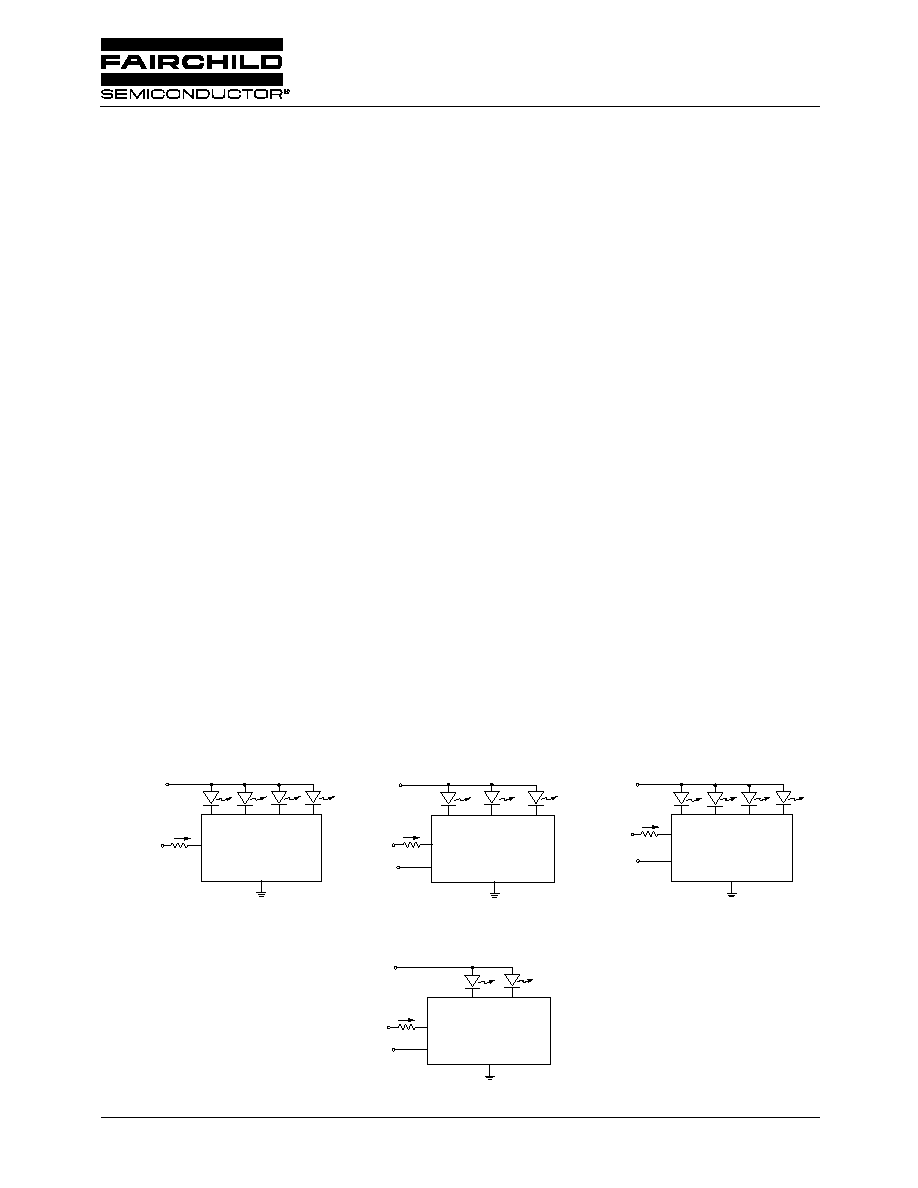
Typical Applications
I
SET
R
SET
I1
I2
I3
I4
V
IN
GND
FAN5611
Four Diode Control
CTRL
V
CONTROL
(3V
)
I
SET
R
SET
I1
I2
I3
I4
V
IN
GND
FAN5613
Four Diode Control With ON/OFF
CTRL
V
CONTROL
(3V)
ENABLE
ON/OFF
R
SET
Two Diode Control with ON/OFF
I3/I4
I1/I2
V
IN
GND
FAN5614
CTRL
V
CONTROL
(3V)
I
SET
ON/OFF
ENABLE
R
SET
Three Diode Control with ON/OFF
I1
I2
I3
V
IN
GND
FAN5612
CTRL
V
CONTROL
(3V)
I
SET
ON/OFF
ENABLE
Features
∑ LED Drivers for parallel-connected LEDs
∑ Ultra-low voltage drop (< 300mV) to support direct
Li-ion applications
∑ No EMI, no switching noise
∑ No external components needed for current matching
∑ Both analog and PWM brightness control
∑ FAN5611, FAN5613 feature up to 160mA bias current
(up to 40mA for each LED)
∑ FAN5612 features up to 120mA bias current (up to 40mA
for each LED)
∑ FAN5614 features up to 160mA bias current (up to 80mA
for each LED)
∑ Enable/Shutdown control (FAN5612, FAN5613,
FAN5614)
∑ Shutdown current < 1
µ
A
∑ Small footprint SC-70 and 2x2 MLP
Applications
∑ Cell Phones
∑ PDA, DSC, MP3 Players
∑ Handheld Computers
∑ LCD Display Modules
∑ Keyboard Backlight
∑ LED Displays
General Description
The FAN5611/FAN5612/FAN5613/FAN5614 driver family
provides matched current source bias for white, blue or any
color LEDs. The current in the LEDs can be programmed by
an external resistor. The individual LED currents are 200 x
I
SET
, where I
SET
is the current through the external resistor
connected to the CTRL pin. The FAN5611 and the FAN5613
are capable of driving four LEDs, while the FAN5612 can
drive three LEDs. The FAN5614 is designated to drive two
high current LEDs. In any case, at least I1 should be always
connected to an LED in order to have the other LEDs driven
with a matched current to I1.
The FAN5612, FAN5613 and FAN5614 have Enable pin.
When these devices are disabled, the supply current drops to
less than 1
µ
A.
The FAN5611, FAN5612 and FAN5614 drivers are available
in a 6-lead SC-70 package. The FAN5613 is available in an
8-lead MLP package.
FAN5611/FAN5612/FAN5613/FAN5614
Low-Dropout LED Drivers for White, Blue or any
Color LED
FAN5611/FAN5612/FAN5613/FAN5614
PRODUCT SPECIFICATION
2
REV. 1.0.4 6/4/04
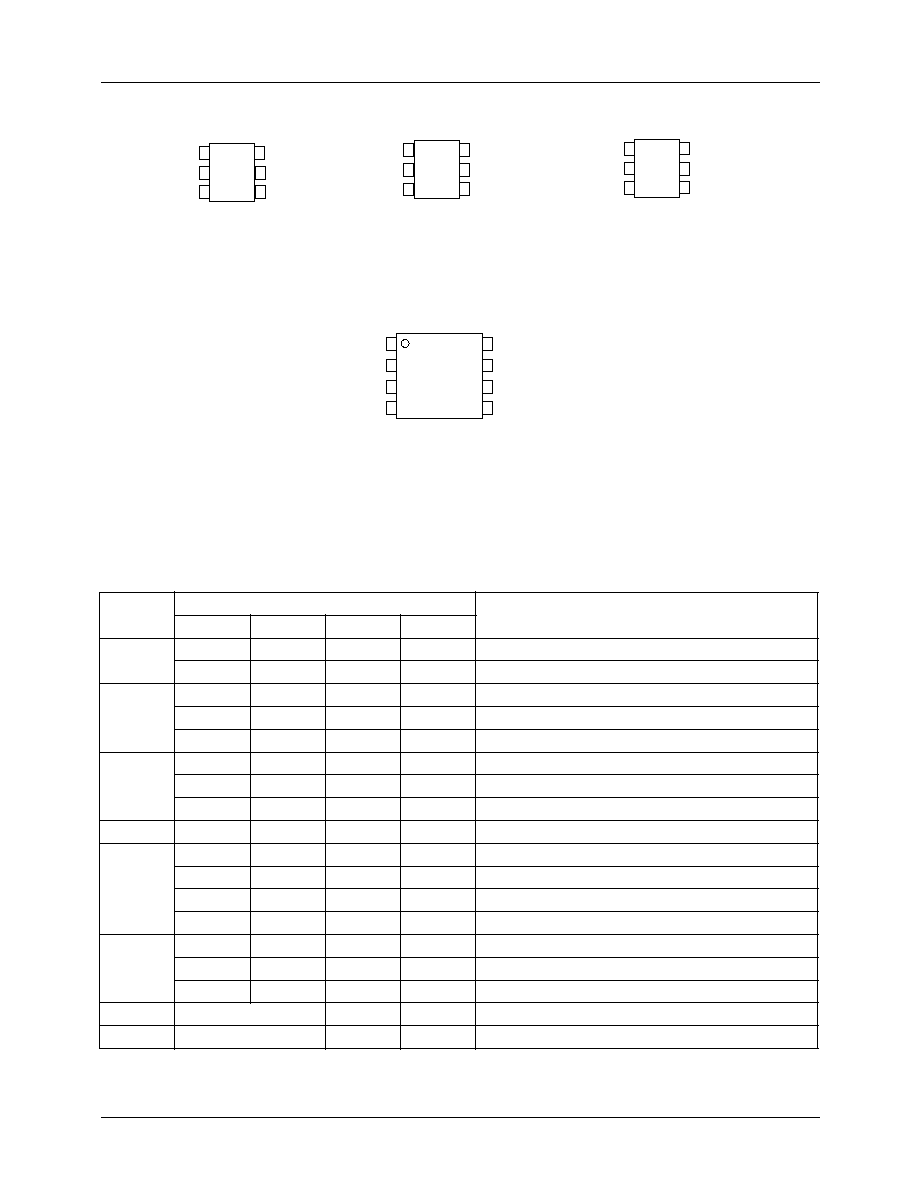
Pin Assignments
Pin Description
(6-Lead SC-70 and 8-Lead MLP)
Pin No.
Pin Name
Description
FAN5611
FAN5612
FAN5613
FAN5614
1
CTRL
CTRL
CTRL
Sets LED Current
ON/OFF
Chip ON/OFF/Disable
2
I2
I2
Connect to Cathode of LED
I3
Connect to Cathode of LED
I1/I2
3
I1
I1
Connect to Cathode of LED
I4
Connect to Cathode of LED
N/C
No Connection
4
GND
GND
GND
GND
Ground
5
I4
Connect to Cathode of LED
I3
Connect to Cathode of LED
I1
Connect to Cathode of LED
I3/I4
Connect to Cathode of LED
6
I3
Connect to Cathode of LED
ON/OFF
ON/OFF
Chip ON/OFF/Disable
I2
Connect to Cathode of LED
7
CTRL
Sets LED Current
8
NC
No Connection
6-LEAD SC-70 PACKAGE
2x2mm 8-LEAD MLP PACKAGE
FAN5613
I2
I4
GND
CTRL
FAN5611
I1
I3
1
3
4
6
2
5
FAN5612
CTRL
I3
GND
I2
I1
ON/OFF
1
3
4
6
2
5
FAN5614
GND
ON/OFF
CTRL
GND
ON/OFF
I4
I3
I2
I1
CTRL
NC
TOP VIEW
1
3
4
6
2
5
N/C
I1/I2
I3/I4
PRODUCT SPECIFICATION
FAN5611/FAN5612/FAN5613/FAN5614
REV. 1.0.4 6/4/04
3
Absolute Maximum Ratings
(Note1)
Recommended Operating Conditions
Notes:
1. Functional operation under these conditions is NOT implied. Performance and reliability are guaranteed only if Operating
Conditions are not exceeded.
2. Using Mil Std. 883E, method 3015.7(Human Body Model) and EIA/JESD22C101-A (Charge Device Model)
Parameter
Min
Max
Unit
V
I1
, V
I2
, V
I3
, V
I4
and ENABLE Voltage to GND
-0.3
6
V
CTRL Voltage to GND
-0.3
3
Power Dissipated by package at T
A
= 85∞C
6 Lead-SC70
190
mW
8 Lead-MLP2X2
700
I1, I2, I3, I4 Steady State Current
FAN5611/12/13
40
mA
I1/I2, I3/I4 Steady State Current
FAN5614
80
Lead Temperature (Soldering 10 seconds)
300
∞C
Junction Temperature
150
∞C
Storage Temperature
-55
150
∞C
Electrostatic Discharge Protection (ESD) Level
(Note2)
HBM
4
kV
CDM
1
Parameter
Min
Typ
Max
Unit
LED Cathode Voltage
FAN5611, FAN5612, FAN5613
0.3
0.5
1
V
FAN5614
0.15
Ambient Temperature
-40
25
85
∞C
FAN5611/FAN5612/FAN5613/FAN5614
PRODUCT SPECIFICATION
4
REV. 1.0.4 6/4/04
DC Electrical Characteristics
(V
IN
= 3.3V to 5.5V, ENABLE = V
IN
, T
A
= 25∞C Unless otherwise noted)
Notes:
3. ENABLE "ON" is V
EN
for which I
I1
>20mA @ V
I1
=0.3V, while ENABLE "OFF" is V
EN
for which I
I1
<1
µ
A @ V
I1
>0.3V
Parameter
Conditions
Min.
Typ.
Max.
Units
Output Current
Multiplication Ratio
FAN5611/12/13
I
SET
= 100µA
V
SAT
= 300mV
140
200
260
FAN5614
I
SET
= 100µA
V
SAT
= 150mV
LED Current (Per Diode) FAN5611/12/13
V
SAT
= 300mV
I
SET
= 100µA
20
mA
FAN5614
V
SAT
= 150mV
I
SET
= 100µA
LED to LED Current
Matching
FAN5611/12/13
V
SAT
= 300mV
I
SET
= 100µA
T
A
= -40∞C to
85∞C
-3
3
%
FAN5614
V
SAT
= 150mV
I
SET
= 100µA
T
A
= -40∞C to
85∞C
Peak Efficiency
V
IN
= 3V
90
%
Current in OFF Mode (I
SET
and
I
I
)
V
EN
= 0V
1
µA
Min. ENABLE "ON Voltage" (Note3)
(FAN5612, FAN5613, FAN5614)
I
SET
= 150µA
3
V
Max. ENABLE "OFF Voltage" (Note3)
(FAN5612, FAN5613 FAN5614)
0.5
V
PRODUCT SPECIFICATION
FAN5611/FAN5612/FAN5613/FAN5614
REV. 1.0.4 6/4/04
5
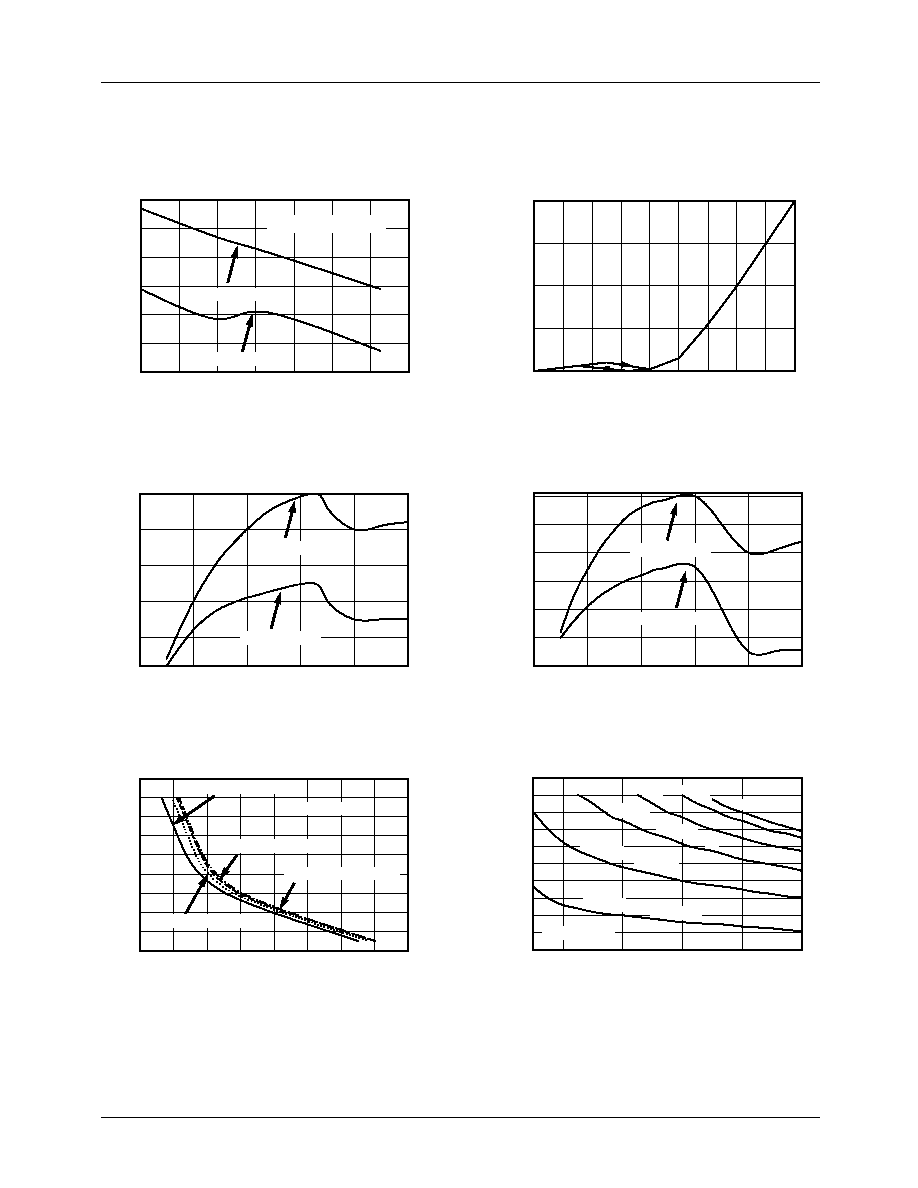
Typical Performance Characteristics
Ambient Temperature (∞C)
LED Cathode Voltage (V)
Set Resistor (K
)
Set Resistor (K
)
LED Cathode Voltage (V)
V
CTRL
(V)
Output Current (mA)
LED Current (mA)
LED Current (mA)
LED Current (mA)
LED Current (mA)
12
-40
-20
0
20
40
60
80
100
0.0
0.2
0.4
0.6
0.8
1.0
0.0
0.2
0.4
0.6
0.8
1.0
0.0
0.2
0.4
0.6
0.8
1.0
0
20
40
60
80
100
20
40
60
80
100
120
140
160
1.2
1.4
1.6
1.8
14
16
18
20
22
24
4
6
8
10
12
14
16
18
20
22
Output Current vs. Temperature
I
SET
vs. V
CTRL
I
SET
(µ
A)
0
50
100
150
200
0
10
15
20
25
30
2
4
6
8
10
12
14
16
18
20
22
5
10
15
20
25
30
35
FAN5614
LED Current vs. LED Cathode Voltage
FAN5611_12_13
LED Current vs. LED Cathode Voltage
FAN5614
LED Current vs. Set Resistor
FAN5611_12_13
LED Current vs. Set Resistor
Cathode Voltage = 0.3V
FAN5611_12_13
For I
SET
= 0.1mA
For I
SET
= 100µA
For I
SET
= 50µA
For I
SET
= 50µA
For I
SET
= 25µA
For I
SET
= 0.05mA
Cathode Voltage = 0.3V
Cathode
Voltage = 0.15V
Cathode Voltage
= 0.10V
Cathode
Voltage = 0.05V
Cathode Voltage = 0.5V
V
CONTROL
= 3V
V
CONTROL
= 3V
Cathode Voltage = 0.6V
Cathode Voltage = 0.4V
0.3V
0.25V
0.20V