©2005 Fairchild Semiconductor Corporation
www.fairchildsemi.com
Rev. 1.0.0
Features
∑ 4-CH H-Bridge driver
∑ Built-in DC-DC converter controller
∑ Built-in Power-on reset (POR) circuit
∑ Built-in battery charging circuit
∑ Built-in battery voltage monitoring circuit
∑ Built-in thermal shutdown (TSD) circuit
∑ Built-in general OP-Amplifier
∑ Low power consumption
∑ Built-in power controller circuit
Description
FAN8038C is monolithic IC for portable CD player, and
suitable for a 4-CH motor driver which drives focus acutator,
tracking actuator, sled motor and spindle motor of portable
CD player system. And it also provides DC-DC converter,
reset, recharge, and short circuit protection.
44-QFP-1010B
Typical application
∑ Portable Compact Disk Player (CDP)
∑ Portable Mini Disk Player (MD)
∑ Disc-Man
∑ Other Potable Compact Disk Media
Ordering Information
Device
Package
Operating Temp.
FAN8038C
44-QFP-1010B
-35
∞
C ~ +85
∞
C
FAN8038C
4-Channel Motor Drive IC

FAN8038C
3
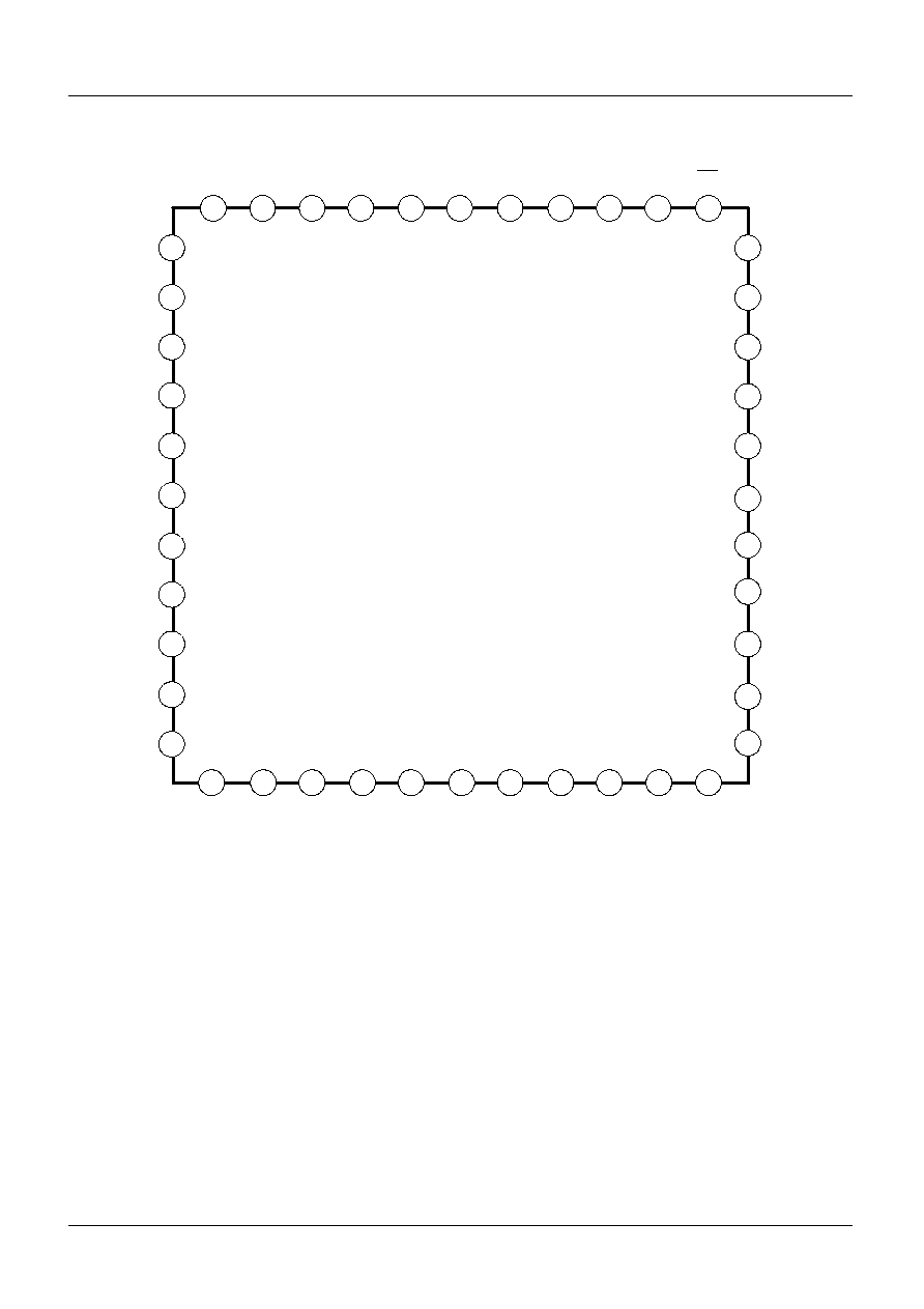
Pin Definitions
Pin Number
Pin Name
I/O
Pin Function Description
1
OVP
I
Battery voltage motor
2
BATT
-
Battery power supply input
3
RSTOUT
O
Power-on reset output
4
DEDSET
I
Dead time setting capacitor
5
BDSW
O
Transistor drive for voltage step-up
6
ERRO
O
Error amplifier output
7
ERRI
I
Error amplifier Input
8
SCP
I
Short circuit protection time setting capacitor
9
COSC
O
Triangular waveform output
10
N.C
-
No connection
11
OPIN(-
)
I
OP-amplifier negative input
12
SVCC1
-
Control circuit power supply
13
OPOUT
O
OP-amplifier output
14
OPIN(+)
I
OP-amplifier positiveinput
15
SVCC2
-
Pre-driver power supply
16
VREF
I
Reference voltage input
17
DI3
I
Channel 3 control signal Input
18
DI4
I
Channel 4 control signal Input
19
MUTE34
I
Channel 3 and 4 mute signal input
20
DI2
I
Channel 2 control signal Input
21
MUTE2
I
Channel 2 mute signal inpu
22
DI1
I
Channel 1 control signal Input
23
BRAKE
I
Channel 1 brake signal input
24
DO4(-)
O
Channel 4 negative output
25
DO4(+)
O
Channel 4 positive output
26
DO3(-)
O
Channel 3 negative output
27
DO3(+)
O
Channel 3 positive output
28
PGND
-
Power block power Ground
29
DO2(+)
O
Channel 2 positive output
30
DO2(-)
O
Channel 2 negative output
31
DO1(+)
O
Channel 1 positive output
32
DO1(-)
O
Channel 1 negative output
33
CHGSET
I
Charge current setting resistance
34
RST
O
Power-on reset inverting output
35
EMP
O
Battery voltage detection output (Empty detection)
36
DVCC
-
H-Bridge block power supply
37
PWM
O
PWM transistor drive output
38
CLKIN
I
External clock input
39
START
I
DC-DC converter start control input
40
STOP
I
DC-DC converter off control input
41
ADPVCC
-
Charging circuit power supply
42
EMPSET
Empty dection level switch
43
SGND
-
Signal ground
44
FIL
I
PWM phase compensation

FAN8038C
5
Absolute Maximum Ratings (Ta = 25
∞
C)
Recommended Operating Conditions (Ta = 25
∞
C)
Parameter
Symbol
Value
Unit
Maximum supply voltage
V
CC
13.2
V
Maximum output current
I
O
500
mA
Power dissipation
P
D
1.0
W
Operating temperature
T
OPR
-35 ~ +85
∞
C
Stroage temperature
T
STG
-55 ~ +150
∞
C
Parameter
Symbol
Min.
Typ.
Max.
Unit
Charging circuit power supply voltage
ADPVCC
3.0
4.5
8.0
V
Power supply voltage
BATT
1.5
2.4
8.0
V
Control circuit power supply voltage
SVCC1
2.7
3.2
5.5
V
Pre-driver power supply voltage
SVCC2
2.7
3.2
5.5
V
H-Bridge power supply voltage
DVCC
-
PWM
BATT
V
Operating Temperature
Ta
-10
25
70
∞
C


