©2002 Fairchild Semiconductor Corporation
www.fairchildsemi.com
Rev.1.0.3
Features
∑ A wide range of operation voltage: 4V to 15V
∑ Built-in motor lock detector.
∑ Automatic restart function
∑ Alarm output for a motor lock detection
∑ Built-in thermal shut down circuits
∑ Built-in reverse current protection diode
∑ Compact package: 8-SOP-225
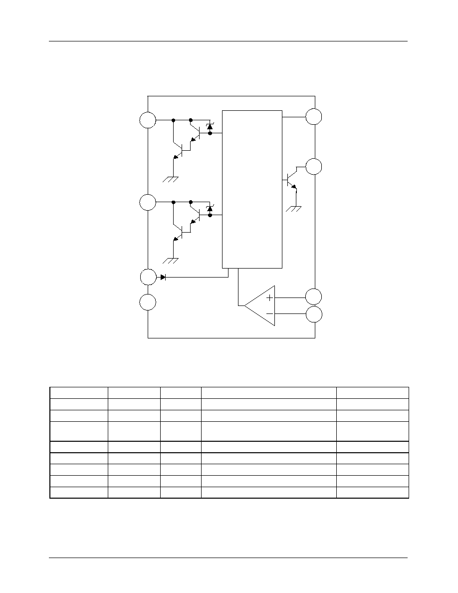
Description
The FAN8404D is a monolithic integrated circuit, and
suitable for DC cooling fan motors.
8-SOP-225
1
Typical Applications
∑ DC cooling fan motor
Ordering Information
Device
Package
Operating Temp.
FAN8404D
8-SOP-225
-
25
∞
C ~ 85
∞
C
FAN8404DTF
8-SOP-225
-
25
∞
C ~ 85
∞
C
FAN8404D
2 Phase Half Wave BLDC Motor Driver

FAN8404D
4
Absolute Maximum Ratings (Ta = 25
∞
C)
Note1:
PCB Condition: Thickness (1.6mm), Dimension (76.2mm * 114.3mm)
Refer: EIA/J SED 51-3 & EIA/J SED 51-7
Note2: Air condition (0m/s)
Note3: Air condition (3m/s)
Note4: Should not exceed P
D
or ASO value
Power Dissipation Curve (Air condition = 0m/s)
Parameter
Symbol
Value
Unit
Maximum power supply voltage
V
CCMAX
18
V
Maximum power dissipation
note1
P
DMAX
429
note2
mW
620
note3
Thermal resistance
note1
JA
291.61
note2
∞
C/W
201.52
note3
Maximum output voltage
V
OMAX
30
V
Maximum output current
I
OMAX
1.2
note4
A
Alarm output current
I
AL
10
mA
Alarm output withstanding voltage
V
AL
36
V
Maximum hall input AC level
V
HACMAX
6
V
Operating temperature
T
OPR
-
25 ~ 85
∞
C
Storage temperature
T
STG
-
55 ~ 150
∞
C
0
0.05
0.1
0.15
0.2
0.25
0.3
0.35
0.4
0.45
0.5
0
20
40
60
80
100
120
140
160
Tc or Ta[∞C]
Pd
[W]

FAN8404D
5
Air Speed &
JA
Recommended Operating Conditions
(Ta = 25
∞
C)
Electrical Characteristics
(Ta=25
∞
C, V
CC
=12V unless otherwise specified)
Parameter
Symbol
Min.
Typ.
Max.
Unit
Function compensation operating voltage
V
CC
4.0
-
15.0
V
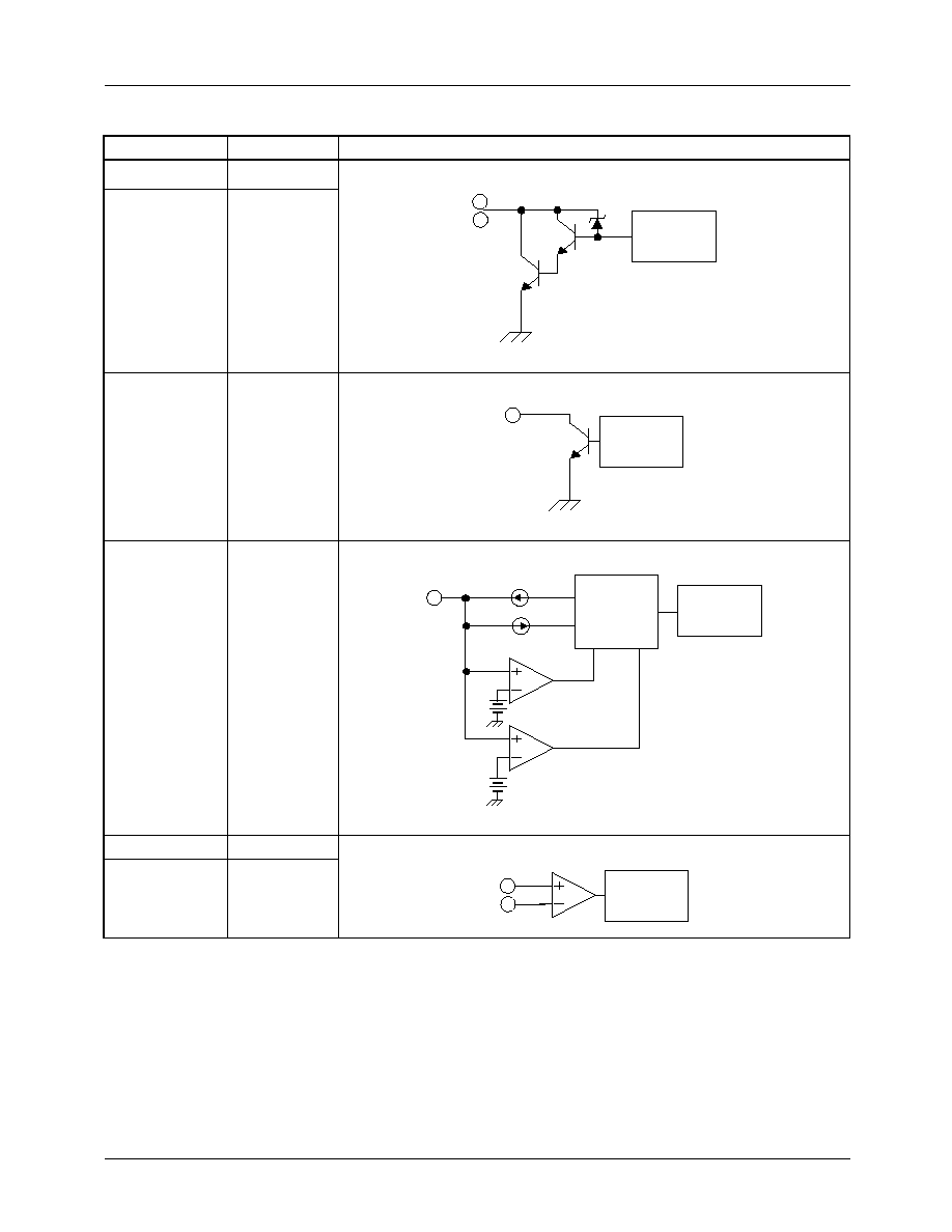
Parameter
Symbol
Conditions
Min.
Typ.
Max. Unit
Supply current
I
CC
When output is off.
-
-
3.0
mA
Lock detector charging current
I
LDC
V
LD
=1.8V
2.38
3.40
4.42
µ
A
Lock detector discharging current
I
LDD
V
LD
=1.8V
0.48
0.68
0.88
µ
A
Lock detector charging/discharging ratio
R
CD
R
CD
=I
LDC
/I
LDD
3.0
5.0
7.0
-
Lock detector capacitor clamp voltage
V
LDCL
-
2.4
2.85
3.3
V
Lock detector capacitor comparator voltage
V
LDCP
-
0.7
0.99
1.2
V
Output low level voltage
V
OL
I
O
=200mA
-
0.9
1.2
V
Output leakage current
I
OL
-
-
0
10
µ
A
Output zener voltage
V
OZ
Clamp current=10mA
28
30
32
V
Alarm output pin low level voltage
V
ALL
I
O
=10mA
-
0.2
0.5
V
Alarm output pin leakage current
I
ALL
-
-
0
10
µ
A
Hall input DC range
V
HDC
-
1
-
V
CC
-
2V
V
Hall Input Offset
V
HOF
V
REF
=6V
-10
-
10
mV
0
50
100
150
200
250
300
350
0
1
2
3
4
5
6
Air Speed[m/s]
JA
[
∞
C
/
W
]