 | –≠–ª–µ–∫—Ç—Ä–æ–Ω–Ω—ã–π –∫–æ–º–ø–æ–Ω–µ–Ω—Ç: FAN8413M | –°–∫–∞—á–∞—Ç—å:  PDF PDF  ZIP ZIP |
©2004 Fairchild Semiconductor Corporation
www.fairchildsemi.com
Rev.1.0.3
Features
∑ A wide range of operation voltage: 4V to 28V
∑ Locked motor protection with open collector
alarm out or speed out and auto retry
∑ Compact package: 8-SOP-225
Description
The FAN8412M/FAN8413M is a monolithic integrated
circuit, and suitable for DC cooling fan motors predriver.
8-SOP-225
1
Typical Applications
∑ DC cooling fan motor
Ordering Information
Note
X : Tape & Reel
NL : Lead Free
Device
Package
Operating Temp.
FAN8412M
8-SOP-225
-40∞C ~ 95∞C
FAN8412MX
8-SOP-225
-40∞C ~ 95∞C
FAN8413M
8-SOP-225
-40∞C ~ 95∞C
FAN8413MX
8-SOP-225
-40∞C ~ 95∞C
FAN8412M_NL
8-SOP-225
-40∞C ~ 95∞C
FAN8412MX_NL
8-SOP-225
-40∞C ~ 95∞C
FAN8413M_NL
8-SOP-225
-40∞C ~ 95∞C
FAN8413MX_NL
8-SOP-225
-40∞C ~ 95∞C
FAN8412M/FAN8413M
2 Phase Half Wave BLDC Motor Predriver

FAN8412M/FAN8413M
2
Block Diagram
Pin Definitions
Pin Number
Pin Name
I/O
Pin Function Description
Remark
1
V
CC
P
Supply voltage
-
2
IN
+
A
Hall input +
-
3
AL
O
Alarm output (For FAN8412M)
Open Collector
TACO
O
Speed output (For FAN8413M)
Open Collector
4
IN
-
A
Hall input
-
-
5
GND
P
Ground
-
6
LD
A
Triangle pulse generator for lock detector
and automatic restart
-
7
OUT
A
A
Motor output A
-
8
OUT
B
A
Motor output B
-
IN-
IN+
TACO
LD
6
3
4
2
V
CC
GND
5
1
OUT
B
OUT
A
8
7
Commutation
& Control
AL /

FAN8412M/FAN8413M
3
Equivalent Circuits
Description
Pin No.
Internal Circuit
OUT
A
7
OUT
B
8
AL /
TACO
3
LD
6
IN+
2
IN-
4
7
8
Commutation
Vcc
Lock detector
3
6
Lock detector
& Automatic
restart
Commutation
V
LDCP
V
LDCL
2
4
Vcc
FAN8412M/FAN8413M
4
Absolute Maximum Ratings (Ta = 25
∞C)
Note1:
PCB Condition: Thickness (1.6mm), Dimension (76.2mm * 114.3mm)
Refer: EIA/J SED 51-2 & EIA/J SED 51-3
Should not exceed P
D
or ASO value
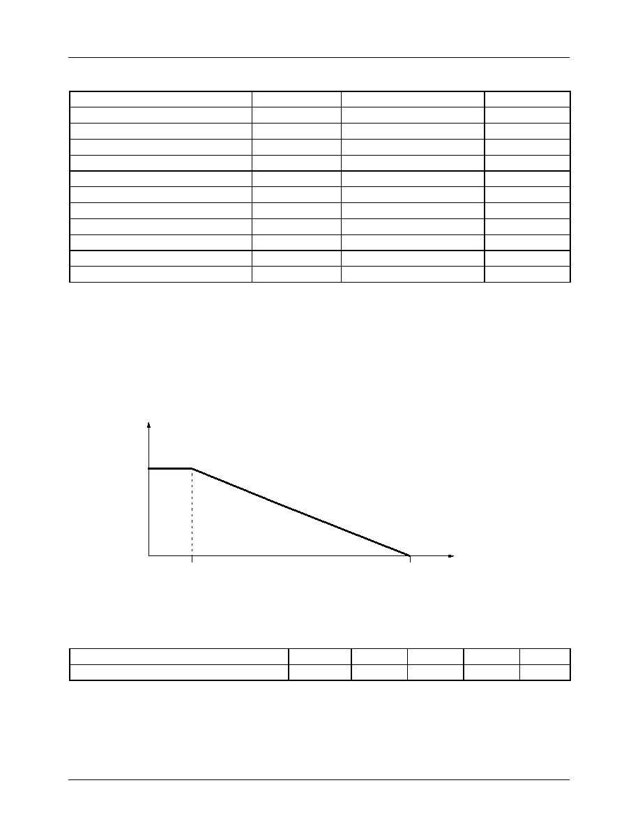
Power Dissipation Curve (Air condition = 0m/s)
Recommended Operating Conditions (Ta = 25
∞C)
Parameter
Symbol
Value
Unit
Maximum Power Supply Voltage
V
CCMAX
32
V
Maximum Power Dissipation
note1
P
DMAX
600
mW
Thermal Resistance
note1
JA
208
∞C/W
Maximum Output Voltage
V
OMAX
36
V
Maximum Output Current
I
OMAX
0.07
A
Alarm Output Current
I
AL
10
mA
Alarm Output Withstanding Voltage
V
AL
36
V
TACO Output Current
I
TACO
10
mA
TACO Output Withstanding Voltage
V
TACO
36
V
Operating Temperature
T
OPR
-40 ~ 95
∞C
Storage Temperature
T
STG
-55 ~ 150
∞C
Parameter
Symbol
Min.
Typ.
Max.
Unit
Function Compensation Operating Voltage
V
CC
4.0
-
28.0
V
Power dissipation (W)
0.6
25
150
Ambient temperature, Ta (
∞C)

FAN8412M/FAN8413M
5
Electrical Characteristics
(Ta=25
∞C, V
CC
=12V unless otherwise specified)
Parameter
Symbol
Conditions
Min.
Typ.
Max. Unit
TOTAL
Supply Current
I
CC
When output is off.
-
3.2
5.0
mA
HALL AMPLIFIER INPUT RANGE
Pin2,4 Hall Input Range
V
HDC
-
1
-
Vcc-2
V
Pin2,4 Hall Input Offest
V
HOF
-
15
-
-
mV
LOCK DETECTOR & AUTO RESTART
Pin6 Lock Detector Charging Current
I
LDC
V
LD
=1.5V
2.2
3.8
5.7
µA
Pin6 Lock Detector Discharging Current
I
LDD
V
LD
=1.5V
0.4
0.88
1.6
µA
Pin6 Lock Detector Charging/Discharging Ratio
R
CD
R
CD
=I
LDC
/I
LDD
3
5
7
-
Pin6 Lock Detector Capacitor Clamp Voltage
V
LDCL
-
2.54
2.94
3.34
V
Pin6 Lock Detector Capacitor Comparator Voltage
V
LDCP
-
0.54
0.74
0.94
V
OUTPUT STAGE
Pin7, 8 Output High Level Voltage
V
OH
I
O
=10mA
10
10.5
-
V
Pin7, 8 Output Low Level Voltage
V
OL
I
O
=10mA
-
-
0.5
V
AL / TACO OUTPUT
Pin3 Alarm Output Low Level Voltage
V
ALL
I
O
=10mA
-
0.2
0.5
V
Pin3 Alarm Output Current Capacity
I
AL
V
AL
=2.0V
8
-
-
mA
Pin3 Taco Output Low Level Voltage
V
TACOL
I
O
=10mA
-
0.2
0.5
V
Pin3 Taco Output Current Capacity
I
TACOL
V
TACO
=2.0V
8
-
-
mA