 | –≠–ª–µ–∫—Ç—Ä–æ–Ω–Ω—ã–π –∫–æ–º–ø–æ–Ω–µ–Ω—Ç: FDLL300A | –°–∫–∞—á–∞—Ç—å:  PDF PDF  ZIP ZIP |

FDH/FDLL 300/A / 333
High Conductance Low Leakage Diode
Sourced from Process 1M. See MMBD1501/A-1505/A for characteristics.
Absolute Maximum Ratings*
TA = 25∞C unless otherwise noted
*
These ratings are limiting values above which the serviceability of any semiconductor device may be impaired.
NOTES:
1) These ratings are based on a maximum junction temperature of 200 degrees C.
2) These are steady state limits. The factory should be consulted on applications involving pulsed or low duty cycle operations.
Thermal Characteristics
TA = 25∞C unless otherwise noted
Symbol
Parameter
Value
Units
W
IV
Working Inverse Voltage
125
V
I
O
Average Rectified Current
200
mA
I
F
DC Forward Current
500
mA
i
f
Recurrent Peak Forward Current
600
mA
i
f(surge)
Peak Forward Surge Current
Pulse width = 1.0 second
Pulse width = 1.0 microsecond
1.0
4.0
A
A
T
stg
Storage Temperature Range
-65 to +200
∞
C
T
J
Operating Junction Temperature
175
∞
C
Symbol
Characteristic
Max
Units
FDH/FDLL 300/A / 333
P
D
Total Device Dissipation
Derate above 25
∞
C
500
3.33
mW
mW/
∞
C
R
JA
Thermal Resistance, Junction to Ambient
300
∞
C/W
COLOR BAND MARKING
DEVICE
1ST BAND
2ND BAND
FDLL300
BROWN
GREEN
FDLL300A
BROWN
YELLOW
FDLL333
BROWN
BLUE
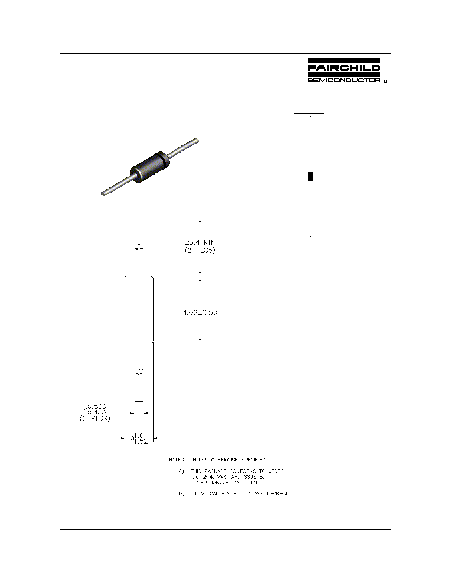
LL-34
THE PLACEMENT OF THE EXPANSION GAP
HAS NO RELATIONSHIP TO THE LOCATION
OF THE CATHODE TERMINAL
DO-35
FDH300/A / FDLL300/A / FDH333 / FDLL333
„
1997 Fairchild Semiconductor Corporation

Electrical Characteristics
TA = 25∞C unless otherwise noted
Symbol
Parameter
Test Conditions
Min
Max
Units
B
V
Breakdown Voltage
I
R
= 100
µ
A
150
V
I
R
Reverse Current
FDH/FDLL 300/A
FDH/FDLL 333
V
R
= 125 V
V
R
= 125 V, T
A
= 150
∞
C
V
R
= 125 V
V
R
= 125 V, T
A
= 100
∞
C
1.0
3.0
3.0
500
nA
µ
A
nA
nA
V
F
Forward Voltage
FDH/FDLL 300/A
FDH/FDLL 300
FDH/FDLL 300A
FDH/FDLL 300/A
FDH/FDLL 300
FDH/FDLL 300A
FDH/FDLL 300/A
FDH/FDLL 300/A
FDH/FDLL 333
I
F
= 1.0 mA
I
F
= 5.0 mA
I
F
= 5.0 mA
I
F
= 10 mA
I
F
= 50 mA
I
F
= 50 mA
I
F
= 100 mA
I
F
= 200 mA
I
F
= 50 mA
I
F
= 100 mA
I
F
= 150 mA
I
F
= 200 mA
I
F
= 250 mA
I
F
= 300 mA
800
830
860
0.87
0.88
0.9
680
750
760
800
880
890
920
1.0
890
940
970
1.05
1.08
1.15
mV
mV
mV
mV
mV
mV
mV
V
mV
mV
mV
V
V
V
C
O
Diode Capacitance
V
R
= 0, f
= 1.0 MHz
6.0
pF
FDH300/A / FDLL300/A / FDH333 / FDLL333
High Conductance Low Leakage Diode
(continued)

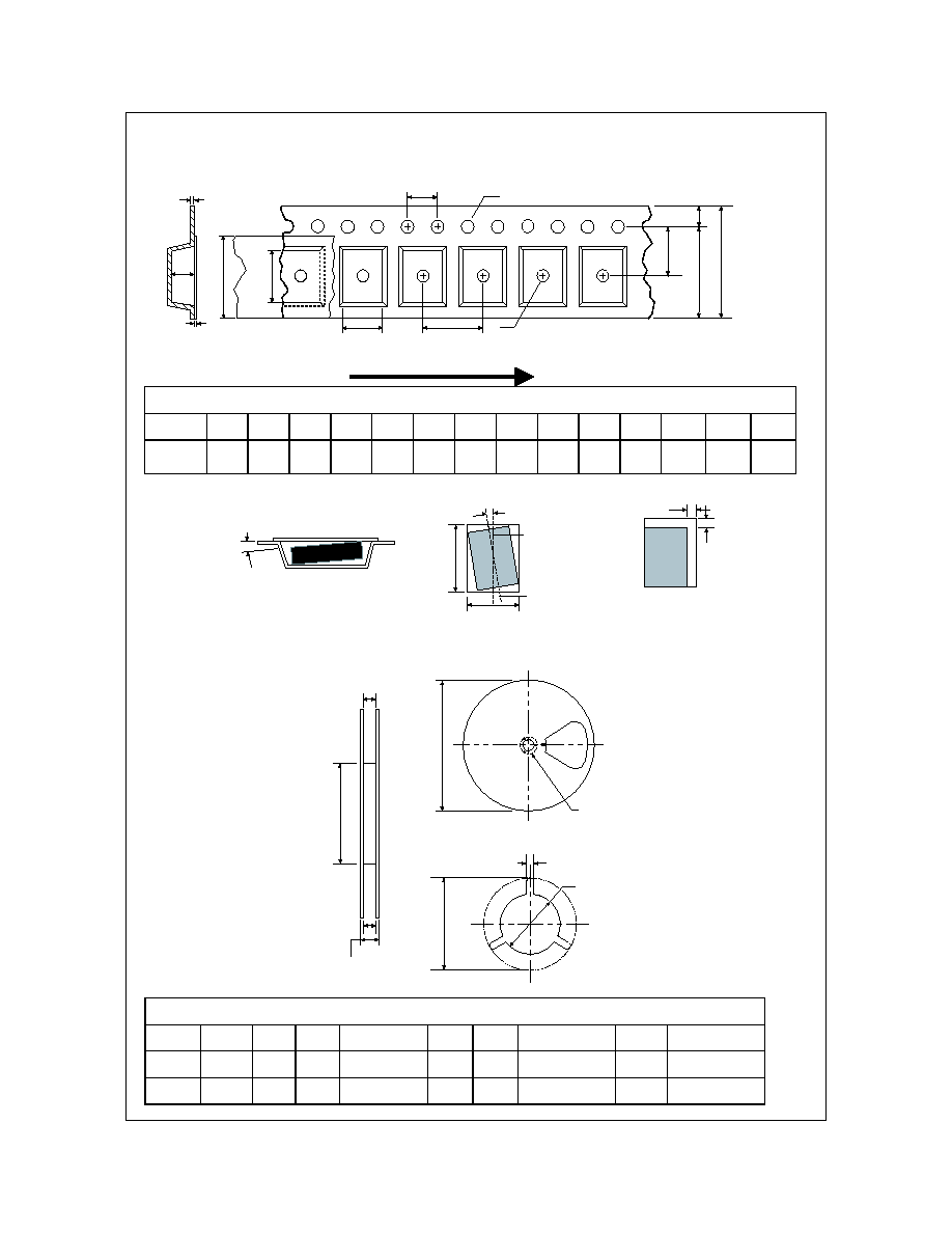
DO-35 Tape and Reel Data
September 1999, Rev. A
DO-35 Packaging Information
T50R
TNR
13
10,000
254x79x794
30,000
0.137
2.23
Note/Comments
Packaging Option
Packaging type
Reel Size (inch diameter)
Qty per Reel/Tube/Bag
Int Box Dimension (mm)
Max qty per Box
Weight per unit (gm)
Weight per Reel/Ammo (kg)
Inside Tape Spacing (mm)
52
T50A
Ammo
-
5,000
406x267x184
50,000
0.137
0.800
52
Bulk
Standard
(no flow code)
Bag
-
500
279x133x108
5,000
0.137
-
-
DO-35 Packaging
Configuration: Figure 1.0
Soabar Label sample
P.O. No.
TYPE
IN5225A
MARK
BLK-BRN
REV
A2
PART No.
PKG
EC No.
QTY
10,000
M.O. No.
OX5046F035
Q.C.
DATE
D9903
MFD. UNDER US PAT 3.025.589 & OTHER US PATS & APPLICATIONS
Kraft Paper Wound
Between Layers
Corrugated Outer Liner
Red/Blue (Cathode)
White (Anode)
Soabar Label
DO-35 Packaging
Information Table: Figure 2.0
T50R
TNR Options
REEL DIMENSIONS
ITEM DESCRIPTION
SYMBOL
MINIMUM
MAXIMUM
Reel Diameter
D1
10.375
10.625
Arbor Hole Diameter (Standard)
D2
1.245
1.255
Core Diameter
D3
3.190
3.310
Flange to Flange Inner Width
W1
3.400
Note: All Dimensions are in inches
D1
D3
W1
D2
DO-35 Reel Dimensions:
Figure 3.0
Soabar Label
©2000 Fairchild Semiconductor International

DO-35 Tape and Ammo Data, continued
September 1999, Rev. A
TAPING DIMENSIONS
INCH
MM
MILS
NOTES
A
2.520
64.00
2519
Overall width
+0.066/
+1.69/
+66.5/
-0.027
-0.69
-27.0
B
2.047
±
0.027
52
±
0.69
2047
±
27
Inside Tape Spacing
C
0.200
±
0.0157
5.08
±
0.40
200
±
15.7
Component Pitch
D
0.047(max)
1.2(max)
47(max)
Component Misalignment
E
0.022(max)
0.55(max)
22(max)
Tape Mismatch
F
0.027(max)
±
0.69
±
27
Units in line w/ one another
G
0.126(min)
3.2(min)
126(min)
Lead amount between tapes
H
0
0
0
Lead amount beyond tapes
L1-L2
±
0.027
±
0.69
±
27
Delta between two leads
254mm x 79mm x 79mm
Intermediate Container (5,000 cap)
T50A Option
DO-35 A mmo Packing
Configuration: Figure 4.0
A
F
C
D
L2
L1
E
B
G
H
DO-35 Bulk Packing
Configuration: Figure 6.0
133mm x 95mm
Anti-static bag (500/bag)
Im
102mm x 76mm x 127mm
mediate Box (1,000 cap)
DO-35 Taping
Dimension: Figure 5.0
Soabar Label
(on top of box)
DO-35 (FS PKG Code D2)
DO-35 Package Dimensions
March 2000, Rev. A
1:1
Scale 1:1 on letter size paper
Dimensions shown below are in millimeters
Part Weight per unit (gram): 0.137
©2000 Fairchild Semiconductor International

LL-34 Tape and Reel Data
January 2000, Rev. B
LL-34 Packaging
Configuration: Figure 1.0
Components
Leader Tape
500mm minimum or
125 empty pockets
Trailer Tape
300mm minimum or
75 empty pockets
Cover Tape
Carrier Tape
Soabar Label
Soabar
Label
Soabar Label sample
P.O. No.
TYPE
FDLL4148
MARK
BLK-BRN
REV
A2
PART No.
PKG
EC No.
QTY
2,500
M.O. No.
OX5046F035
Q.C.
DATE
D9903
MFD. UNDER US PAT 3.025.589 & OTHER US PATS & APPLICATIONS
Cathode
Note/Comments
Packaging Option
LL-34 Packaging Information
Standard
(no flow c ode)
Packaging type
Reel Size
TNR
7" Dia
Qty per Reel/Tube/Bag
2,500/1,000 (bulk)
Box Dimension (mm)
190x190x90
Max qty per Box
15,000
Weight per unit (gm)
0.030
Weight per Reel (kg)
0.150
Static Dissipative Embossed
Carrier Tape
Soabar Label
Antistatic Cover Tape
LL-34 Tape Leader and Trailer
Configuration: Figure 2.0
Packaging Description:
LL-34 parts are shipped in tape. The carrier tape is made
from a dissipative (carbon filled) polycarbonate resin. The
cover tape is a multilayer film (Heat Activated Adhesive in
nature) primarily composed of polyester film, adhesive
layer, sealant, and anti-static sprayed agent. These reeled
parts in standard option are shipped with 2,500 units per
7" or 178cm diameter reel. The reels are white in color and
is made of recyclable chipboard. Other option comes in
10,000 units per 13" or 330cm diameter reel. This and
some other options are described in the Packaging
Information table.
These full reels are individually labeled and placed inside
a bleach box (illustrated in figure 1.0) made of recyclable
corrugated paper. One bleach box contains six reels
maximum. These bleach boxes are placed inside a
labeled shipping box which comes in different sizes
depending on the number of reels shipped.
LL-34 Unit Orientation
©2000 Fairchild Semiconductor International
LL-34 Tape and Reel Data,continued
January 2000, Rev. B
7" Diameter Option
Dim A
Max
See detail AA
W3
W2 max Measured at Hub
W1 Measured at Hub
Dim N
Dim D
min
Dim C
B Min
DETAIL AA
LL-34 Carton Reel Configuration: Figure 4.0
Dimensions are in inches and millimeters
Tape Size
Reel
Option
Dim A
Dim B
Dim C
Dim D
Dim N
Dim W1
Dim W2
Dim W3 (LSL-USL)
8mm
7" Dia
7.00
178
0.059
1.5
512 +0.020/-0.008
13 +0.5/-0.2
0.795
20.2
2.165
55
0.331 +0.059/-0.000
8.4 +1.5/0
0.567
14.4
0.311 ≠ 0.429
7.9 ≠ 10.9
8mm
13" Dia
13.00
330
0.059
1.5
512 +0.020/-0.008
13 +0.5/-0.2
0.795
20.2
4.00
100
0.331 +0.059/-0.000
8.4 +1.5/0
0.567
14.4
0.311 ≠ 0.429
7.9 ≠ 10.9
Dimensions are in millimeter
Pkg type
A0
B0
W
D0
D1
E1
E2
F
P1
P0
K0
T
Wc
Tc
LL-34
(8mm)
1.7
+/-0.10
3.7
+/-0.10
8.0
+/-0.3
1.5
+/-0.10
1.1
+/-0.10
1.75
+/-0.10
6.25
min
3.50
+/-0.05
4.0
+/-0.1
4.05
+/-0.05
1.7
+/-0.10
0.3
+/-0.05
5.5
+/-0.2
0.10
max
Notes: A0, B0, and K0 dimensions are determined with respect to the EIA/Jedec RS-481
rotational and lateral movement requirements (see sketches A, B, and C).
20 deg maximum component rotation
0.5mm
maximum
0.5mm
maximum
Sketch C (Top View)
Component lateral movement
Typical
component
cavity
center line
20 deg maximum
Typical
component
center line
B0
A0
Sketch B (Top View)
Component Rotation
Sketch A (Side or Front Sectional View)
Component Rotation
LL-34 Embossed Carrier Tape
Configuration: Figure 3.0
P1
A0
D1
P0
F
W
E1
D0
E2
B0
Tc
Wc
K0
T
User Direction of Feed

LL-34 (FS PKG Code D3)
LL-34 Package Dimensions
March 2000, Rev. A
1:1
Scale 1:1 on letter size paper
Dimensions shown below are in millimeters
Part Weight per unit (gram): 0.030
©2000 Fairchild Semiconductor International
TRADEMARKS
The following are registered and unregistered trademarks Fairchild Semiconductor owns or is authorized to use and is
not intended to be an exhaustive list of all such trademarks.
LIFE SUPPORT POLICY
FAIRCHILD'S PRODUCTS ARE NOT AUTHORIZED FOR USE AS CRITICAL COMPONENTS IN LIFE SUPPORT
DEVICES OR SYSTEMS WITHOUT THE EXPRESS WRITTEN APPROVAL OF FAIRCHILD SEMICONDUCTOR CORPORATION.
As used herein:
1. Life support devices or systems are devices or
systems which, (a) are intended for surgical implant into
the body, or (b) support or sustain life, or (c) whose
failure to perform when properly used in accordance
with instructions for use provided in the labeling, can be
reasonably expected to result in significant injury to the
user.
2. A critical component is any component of a life
support device or system whose failure to perform can
be reasonably expected to cause the failure of the life
support device or system, or to affect its safety or
effectiveness.
PRODUCT STATUS DEFINITIONS
Definition of Terms
Datasheet Identification
Product Status
Definition
Advance Information
Preliminary
No Identification Needed
Obsolete
This datasheet contains the design specifications for
product development. Specifications may change in
any manner without notice.
This datasheet contains preliminary data, and
supplementary data will be published at a later date.
Fairchild Semiconductor reserves the right to make
changes at any time without notice in order to improve
design.
This datasheet contains final specifications. Fairchild
Semiconductor reserves the right to make changes at
any time without notice in order to improve design.
This datasheet contains specifications on a product
that has been discontinued by Fairchild semiconductor.
The datasheet is printed for reference information only.
Formative or
In Design
First Production
Full Production
Not In Production
DISCLAIMER
FAIRCHILD SEMICONDUCTOR RESERVES THE RIGHT TO MAKE CHANGES WITHOUT FURTHER
NOTICE TO ANY PRODUCTS HEREIN TO IMPROVE RELIABILITY, FUNCTION OR DESIGN. FAIRCHILD
DOES NOT ASSUME ANY LIABILITY ARISING OUT OF THE APPLICATION OR USE OF ANY PRODUCT
OR CIRCUIT DESCRIBED HEREIN; NEITHER DOES IT CONVEY ANY LICENSE UNDER ITS PATENT
RIGHTS, NOR THE RIGHTS OF OTHERS.
PowerTrench
QFETTM
QSTM
QT OptoelectronicsTM
Quiet SeriesTM
SILENT SWITCHER
SMART STARTTM
SuperSOTTM-3
SuperSOTTM-6
SuperSOTTM-8
FASTrTM
GlobalOptoisolatorTM
GTOTM
HiSeCTM
ISOPLANARTM
MICROWIRETM
OPTOLOGICTM
OPTOPLANARTM
PACMANTM
POPTM
Rev. G
ACExTM
BottomlessTM
CoolFETTM
CROSSVOLTTM
DOMETM
E
2
CMOS
TM
EnSigna
TM
FACTTM
FACT Quiet SeriesTM
FAST
SyncFETTM
TinyLogicTM
UHCTM
VCXTM