 | –≠–ª–µ–∫—Ç—Ä–æ–Ω–Ω—ã–π –∫–æ–º–ø–æ–Ω–µ–Ω—Ç: GBPC25 | –°–∫–∞—á–∞—Ç—å:  PDF PDF  ZIP ZIP |
GBPC 12, 15, 25, 35 SERIES
GBPC 12, 15, 25, 35 SERIES , Re
v . A
GBPC 12, 15, 25, 35 SERIES
12, 15, 25, 35 Ampere Glass Passivated Bridge Rectifiers
Absolute Maximum Ratings*
T
A
= 25∞C unless otherwise noted
*
These ratings are limiting values above which the serviceability of any semiconductor device may be impaired.
©
1999 Fairchild Semiconductor Corporation
Features
∑
Integrally molded heatsink
provided very low thermal
resistance for maximum
heat dissipation.
∑
Surge overload rartings
from 300 amperes to
400 amperes.
∑
Isolated voltage from case
to lead over 2500 volts.
Symbol Parameter
Value Units
I
O
Averag e Rectified Curr
en t GBPC12
@ T
A
= 55
∞
C
GBPC15
GBPC25
GBPC35
12
15
25
35
A
A
A
A
i
f(surge)
Peak F or w ard Surge C u rrent
8.3 m s single half-
sine- w a ve
GBPC12, 15, 25
Superimposed on rate
d load (JEDEC method
)
GBPC35
300
400
A
A
P
D
Total D evice Dissipati
on
Derate a bove 2 5
∞
C
83.3
666
W
m W/
∞
C
R
JL
Ther m a l Resistance, J u nction to Lead
1.5
∞
C/W
T
stg
Storag e Tem perature Range -55 to +150
∞
C
T
J
Operati n g Junction Temperature
-55 to +150
∞
C
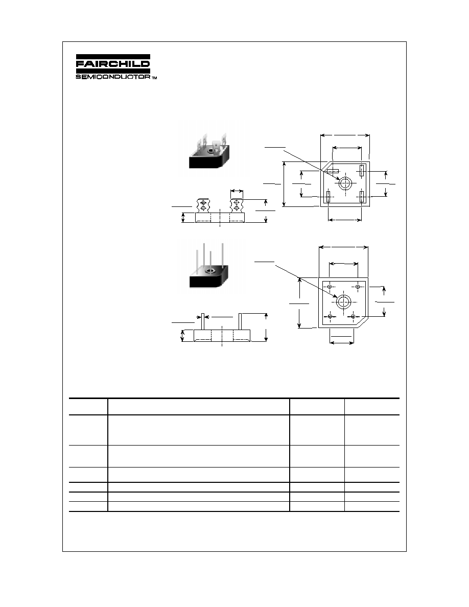
GBPC
GBPC-W
Dimensions are in:
inches (mm)
+
~
~
≠
0.692(17.6)
0.612(15.5)
1.14(29.0)
1.12(28.5)
0.612(15.5)
0.692(17.6)
1.12(28.5)
1.14(29.0)
0.522(13.3)
0.602(15.3)
0.752(19.1)
0.672(17.1)
0.20(5.08)
0.22(5.59)
D I A
H OL E F OR #10 SCR EW
0.25(6.35)
0.432(10.97)
0.442(11.23)
0.85(21.5)
0.96(24.5)
0.432(10.97)
0.442(11.23)
1.2(30.5)
M I N
0.038(0.97)
0.042(1.07)
0.752(19.1)
0.672(17.1)
0.20(5.08)
0.22(5.59)
D I A
H OLE FOR #10 SC R EW
≠
+
~
~
1.12(28.5)
1.14(29.0)
0.490(12.4)
0.410(10.4)
1.14(29.0)
1.12(28.5)
0.672(17.1)
0.752(19.1)
Suffix "W"
Wire Lead Structure
Suffix "M"
Terminal Location
Face to Face
Discrete POWER & Signal
Technologies
GBPC 12, 15, 25, 35 SERIES
GBPC 12, 15, 25, 35 SERIES , Rev. A
Glass Passivated Bridge Rectifiers
(continued)
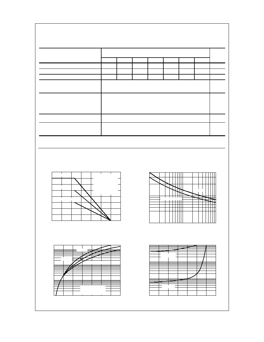
Typical Characteristics
Forward Current Derating Curve
0
25
50
75
100
125
150
175
0
10
20
30
40
AMBIENT TEMPERATURE ( C)
FO
RW
AR
D CU
RRE
NT
(
A
)
∫
SINGLE PHASE
HALF WAVE
60HZ
RESISTIVE OR
INDUCTIVE LOAD
.375" (9.0mm) LEAD
LENGTHS
GBPC35
GBPC25
GBPC12-GBPC15
Non-Repetitive Surge Current
1
2
5
10
20
50
100
20
50
100
200
400
NUMBER OF CYCLES AT 60Hz
PE
AK
F
O
R
W
A
R
D
S
URG
E
CU
RR
ENT
(
A
)
GBPC12-GBPC25
GBPC35
Forward Characteristics
0.6
0.8
1
1.2
1.4
1.6
1.8
2
0.1
1
10
100
200
FORWARD VOLTAGE (V)
F
O
R
W
AR
D CU
RR
E
N
T
(
A
)
Pulse Width = 300
µ
s
2% Duty Cycle
T = 25 C
∫
A
GBPC12-GBPC15
GBPC25
GBPC35
Reverse Characteristics
0
20
40
60
80
100
120
140
0.1
1
10
100
PERCENT OF RATED PEAK REVERSE VOLTAGE (%)
R
EVE
R
S
E
C
U
R
R
EN
T
(
A
)
µ
T = 25 C
∫
A
T = 125 C
∫
A
Electrical Characteristics
T
A
= 25∞C unless otherwise noted
Parameter
Device
Units
005
01
02
04
06
08
10
Peak Repetitive Reverse Voltage
50
100
200
400
600
800
1000
V
Maximum RMS Bridge Input Voltage
35
70
140
280
420
560
700
V
DC Reverse Voltage
(Rated V
R
)
50
100
200
400
600
800
1000
V
Maximum Reverse Leakage,
total bridge @ rated V
R
T
A
= 25
∞
C
T
A
= 125
∞
C
5.0
500
µ
A
µ
A
Maximum Forward Voltage Drop,
per bridge @ 6.0 A
GBPC12
@ 7.5 A
GBPC15
@ 12.5 A
GBPC25
@ 17.5 A
GBPC35
1.1
V
I
2
t rating for fusing
GBPC12,15,25
t < 8.3 ms
GBPC35
375
660
A
2
Sec
A
2
Sec
Typical Junction Capacitance, per leg
V
R
= 4.0V,
GBPC12,15,25
f = 1.0 MHz
GBPC35
180
200
pF
pF

TRADEMARKS
ACExTM
CoolFETTM
CROSSVOLTTM
E
2
CMOS
TM
FACTTM
FACT Quiet SeriesTM
FAST
Æ
FASTrTM
GTOTM
HiSeCTM
The following are registered and unregistered trademarks Fairchild Semiconductor owns or is authorized to use and is
not intended to be an exhaustive list of all such trademarks.
LIFE SUPPORT POLICY
FAIRCHILD'S PRODUCTS ARE NOT AUTHORIZED FOR USE AS CRITICAL COMPONENTS IN LIFE SUPPORT
DEVICES OR SYSTEMS WITHOUT THE EXPRESS WRITTEN APPROVAL OF FAIRCHILD SEMICONDUCTOR CORPORATION.
As used herein:
ISOPLANARTM
MICROWIRETM
POPTM
PowerTrenchTM
QSTM
Quiet SeriesTM
SuperSOTTM-3
SuperSOTTM-6
SuperSOTTM-8
TinyLogicTM
1. Life support devices or systems are devices or
systems which, (a) are intended for surgical implant into
the body, or (b) support or sustain life, or (c) whose
failure to perform when properly used in accordance
with instructions for use provided in the labeling, can be
reasonably expected to result in significant injury to the
user.
2. A critical component is any component of a life
support device or system whose failure to perform can
be reasonably expected to cause the failure of the life
support device or system, or to affect its safety or
effectiveness.
PRODUCT STATUS DEFINITIONS
Definition of Terms
Datasheet Identification Product Status Definition
Advance Information
Preliminary
No Identification Needed
Obsolete
This datasheet contains the design specifications for
product development. Specifications may change in
any manner without notice.
This datasheet contains preliminary data, and
supplementary data will be published at a later date.
Fairchild Semiconductor reserves the right to make
changes at any time without notice in order to improve
design.
This datasheet contains final specifications. Fairchild
Semiconductor reserves the right to make changes at
any time without notice in order to improve design.
This datasheet contains specifications on a product
that has been discontinued by Fairchild semiconductor.
The datasheet is printed for reference information only.
Formative or
In Design
First Production
Full Production
Not In Production
DISCLAIMER
FAIRCHILD SEMICONDUCTOR RESERVES THE RIGHT TO MAKE CHANGES WITHOUT FURTHER
NOTICE TO ANY PRODUCTS HEREIN TO IMPROVE RELIABILITY, FUNCTION OR DESIGN. FAIRCHILD
DOES NOT ASSUME ANY LIABILITY ARISING OUT OF THE APPLICATION OR USE OF ANY PRODUCT
OR CIRCUIT DESCRIBED HEREIN; NEITHER DOES IT CONVEY ANY LICENSE UNDER ITS PATENT
RIGHTS, NOR THE RIGHTS OF OTHERS.