KBL005 - KBL10
KBL005-KBL10, Rev. A
KBL005 - KBL10
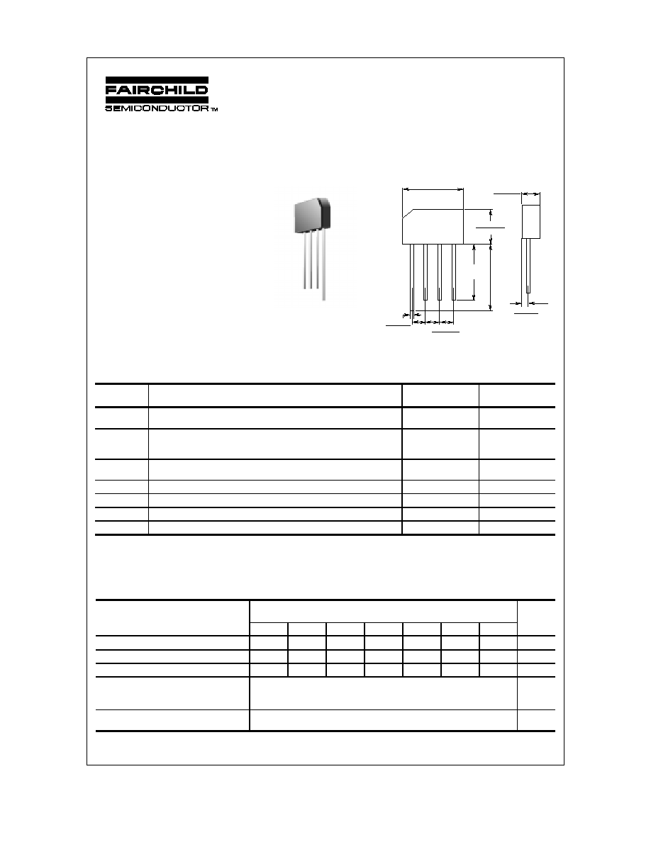
4.0 Ampere Silicon Bridge Rectifiers
Absolute Maximum Ratings*
T
A
= 25∞C unless otherwise noted
Electrical Characteristics
T
A
= 25∞C unless otherwise noted
©
1999 Fairchild Semiconductor Corporation
Features
∑
Ideal for printed circuit board .
∑
Reliable low cost construction.
∑
High surge current capability.
Parameter Device Units
005 01 02 04 06 08 10
Peak Repetitive Reverse Voltage 50 100 200 400 600 800 1000 V
Maximum RMS Bridge Input Voltage 35 70 140 280 420 560 700 V
DC Reverse Voltage
(Rated V
R
) 50 100 200 400 600 800 1000 V
Maximum Reverse Leakage,
total bridge @ rated V
R
T
A
= 25
∞
C
T
A
= 100
∞
C
5.0
500
µ
A
µ
A
Maximum Forward Voltage Drop,
per bridge @ 4.0 A 1.1 V
Symbol Parameter Value Units
I
O
Average Rectified Current
@ T
A
= 40
∞
C
4.0 A
i
f(surge)
Peak Forward Surge Current
8.3 ms single half-sine-wave
Superimposed on rated load (JEDEC method)
200 A
P
D
Total Device Dissipation
Derate above 25
∞
C
6.58
53
W
mW/
∞
C
R
JA
Thermal Resistance, Junction to Ambient,** per leg 19
∞
C/W
R
JL
Thermal Resistance, Junction to Lead,** per leg 2.4
∞
C/W
T
stg
Storage Temperature Range -55 to +150
∞
C
T
J
Operating Junction Temperature -55 to +150
∞
C
0.245(6.22)
0.255(6.48)
0.06(1.52)
0.08(2.0)
+ ~
~
≠
0.605(15.37)
0.645(16.38)
0.73(18.5)
0.77(19.6)
1.0(25.4)
MIN
0.048(1.22)
0.052(1.32)
0.190(4.83)
0.210(5.33)
1.1(27.9)
MIN
Dimensions are in:
inches (mm)
*
These ratings are limiting values above which the serviceability of any semiconductor device may be impaired.
**
Device mounted on PCB with 0.375 " (9.5 mm) lead length and 0.5 x 0.5" (13 x 13 mm) copper pads.
KBL
Discrete POWER & Signal
Technologies
KBL005 - KBL10
KBL005-KBL10, Rev. A
Silicon Bridge Rectifiers
(continued)
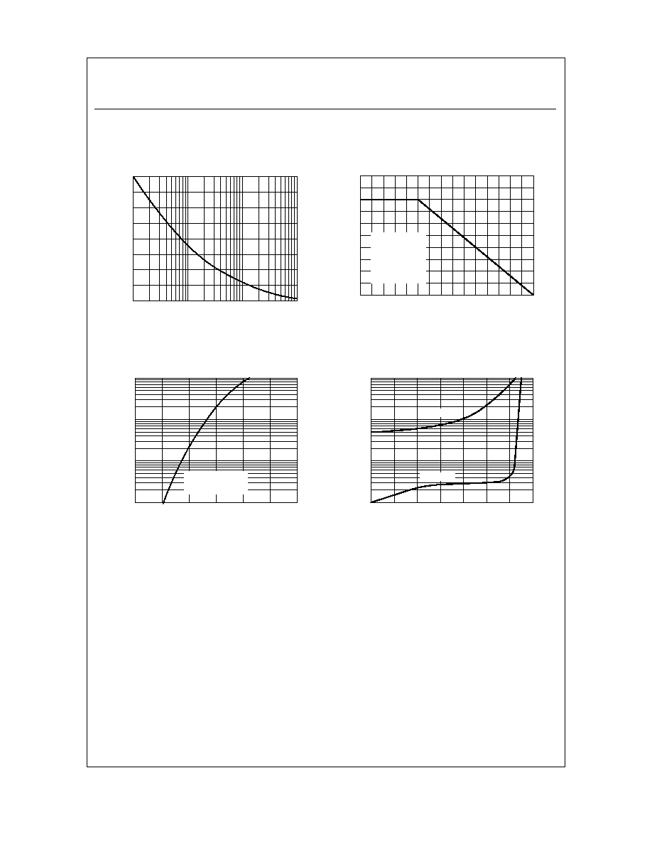
Typical Characteristics
Forward Current Derating Curve
0
50
100
150
0
1
2
3
4
5
AMBIENT TEMPERATURE ( C)
FO
RW
AR
D CU
RRE
NT
(
A
)
∫
SINGLE PHASE
HALF WAVE
60HZ
RESISTIVE OR
INDUCTIVE LOAD
.375" 9.0 mm LEAD
LENGTHS
Forward Characteristics
0.4
0.6
0.8
1
1.2
1.4
1.6
0.01
0.1
1
10
FORWARD VOLTAGE (V)
F
O
R
W
AR
D CU
RR
E
N
T
(
A
)
Pulse Width = 200
µ
S
2% Duty Cycle
T = 25 C
∫
J
Pulse Width = 300
µ
S
2% Duty Cycle
T = 25 C
∫
A
Reverse Characteristics
0
20
40
60
80
100
120
140
0.01
0.1
1
10
PERCENT OF RATED PEAK REVERSE VOLTAGE (%)
R
EVE
R
S
E
C
U
R
R
EN
T
(
A
)
µ
T = 100 C
∫
A
T = 25 C
∫
A
Non-Repetitive Surge Current
1
10
100
1000
0
100
200
NUMBER OF CYCLES AT 60Hz
F
O
R
W
A
R
D
S
URG
E
CU
RR
E
N
T
(
A
)