©2001 Fairchild Semiconductor Corporation
www.fairchildsemi.com
Rev. 1.0.0
Features
∑ Output current in excess of 1.5A
∑ Output voltage adjustable between -1.2V and - 37V
∑ Internal thermal overload protection
∑ Internal short circuit current limiting
∑ Output transistor safe area compensation
∑ Floating operation for high voltage applications
∑ Standard 3-pin TO-220 package
Description
The LM337 is a 3-terminal negative adjustable regulator. It
supplies in excess of 1.5A over an output voltage range of
-1.2V to - 37V. This regulator requires only two external
resistor to set the output voltage. Included on the chip are
current limiting, thermal overload protection and safe area
compensation.
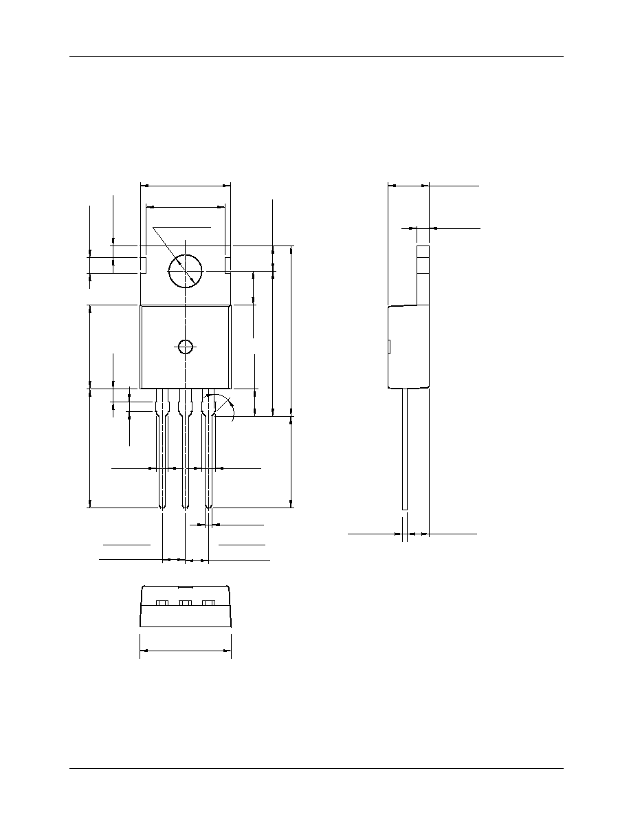
TO-220
1. Adj 2. Input 3. Output
1
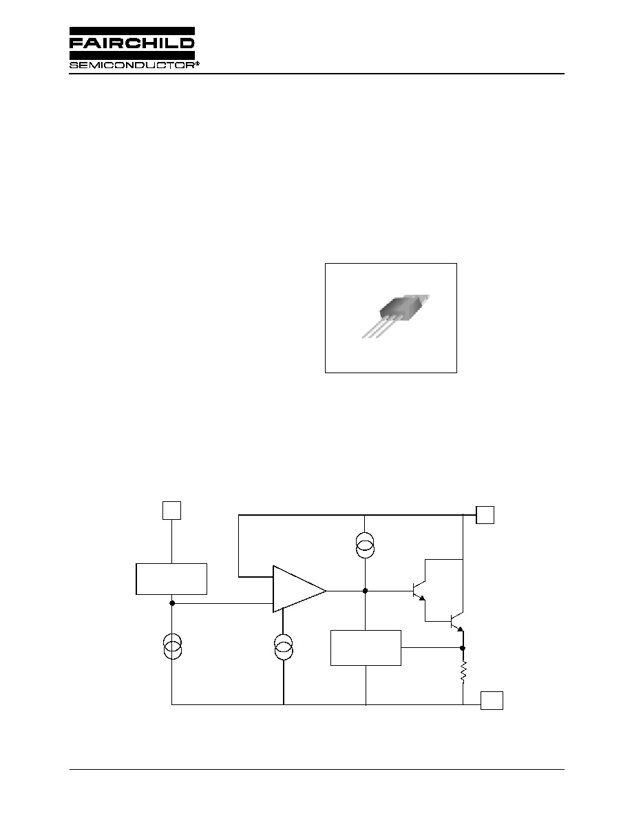
Internal Block Diagram
1
Voltage
Reference
-
+
2
Protection
Circuitry
3
Output
Input
Vadj
LM337
3-Terminal 1.5A Negative Adjustable Regulator

LM337
2
Absolute Maximum Ratings
Electrical Characteristics
(V
I
- V
O
= 5V, I
O
= 40mA, 0
∞
C
T
J
+125
∞
C, P
DMAX
= 20W, unless otherwise specified)
Note:
1. Load and line regulation are specified at constant junction temperature. Change in V
O due to heating effects
must be taken into
account separately. Pulse testing with low duty is used.
2. C
ADJ
, when used, is connected detween the adjustment pin and ground.
Parameter
Symbol
Value
Unit
Input-Output Voltage Differential
|V
I
- V
O
|
40
V
Power Dissipation
P
D
Internally limited
W
Operating Temperature Range
T
OPR
0 ~ +125
∞
C
Storage Temperature Range
T
STG
-65 ~+125
∞
C
Parameter
Symbol
Conditions
Min
Typ.
Max.
Unit
Line Regulation (Note1)
R
line
T
A
= +25
∞
C
3V
I
V
I
- V
O
I
40V
-
0.01
0.04
%/ V
3V
I
V
I
- V
O
I
40V
-
0.02
0.07
Load Regulation (Note1)
R
load
T
A
= +25
∞
C
10mA
I
O
0.5A
-
15
50
mV
10mA
I
O
1.5A
-
15
150
Adjustable Pin Current
I
ADJ
-
-
50
100
µ
A
Adjustable Pin Current Change
I
ADJ
T
A
=+ 25
∞
C
10mA
I
O
1.5A
3V
I
V
I
- V
O
I
40V
-
2
5
µ
A
T
A
=+ 25
∞
C
-1.213
-1.250
-1.287
Reference Voltage
V
REF
3V
I
V
I
- V
O
I
40V
10mA
I
O
1.5A
-1.200
-1.250
-1.300
V
Temperature Stability
ST
T
0
∞
C
J
+
125
∞
C -
0.6
-
%
Minimum Load Current to Maintain
Regulation
I
L(MIN)
3V
I
V
I
- V
O
I
40V
-
2.5
10
3V
I
V
I
- V
O
I
10V
-
1.5
6
mA
Output Noise
e
N
T
A
=+25
∞
C 10Hz
f
10KHz
-
0.003
-
V/10
6
Ripple Rejection Ratio
RR
V
O
= -10V, f = 120Hz
-
60
-
C
ADJ
= 10
µ
F (Note2)
66
77
-
dB
Long Term Stability
ST
T
J
= 125
∞
C ,1000Hours
-
0.3
1
%
Thermal Resistance Junction to
Case
R
JC
-
-
4
-
∞
C/ W
LM337
3
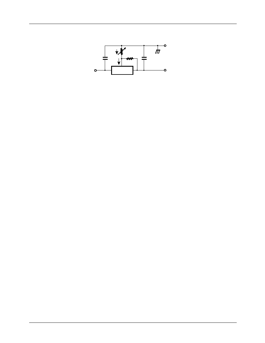
Typical Application
Figure 1. Programmable Regulator
∑ Ci is required if regulator is located more then 4 inches from power supply filter.
A 1.0
µ
F solid tantalum or 10
µ
F aluminum electrolytic is recommended.
Co is necessary for stability. A 1.0
µ
F solid tantalum or 10
µ
F aluminum electrolytic
is recommended.
∑ V
O
= -1.25V (1+R
2
/R
1
)
-V
I
KA337
Ci
0. 1
µ
µ
µ
µ
F
VI
Vo
Vadj
R
2
I
adj
R
1
I
PROG
Co
1
µ
µ
µ
µ
F
-V
o
+
+
LM337