 | ÐлекÑÑоннÑй компоненÑ: RC0431A | СкаÑаÑÑ:  PDF PDF  ZIP ZIP |
Äîêóìåíòàöèÿ è îïèñàíèÿ www.docs.chipfind.ru
www.fairchildsemi.com
REV. 1.0.7 8/5/03
Features
· Low voltage operation to 1.24V
· 1% reference voltage tolerance
· Output voltage adjustable from V
ref
to 12V
· Low 80µA operational cathode current
· 0.25
typical output impedance
· TO-92, SOT23-3 and SOT23-5 packages
Applications
· Voltage reference for discrete power circuits
Description
The RC0431A is a low-voltage 3-terminal adjustable
precision voltage reference regulator. It has an excellent
thermal stability over the standard commercial temperature
range. The output voltage can be set to any value between
Vref (1.24V) and 12V using two external resistors. The
RC0431A operates from a lower voltage (1.24V) than the
traditional shunt regulator references which operate from
2.5V. When used with an optocoupler, the RC0431A will be
an ideal voltage reference in an isolated feedback circuit for
use in switched-mode power supplies and modular DC-DC
converters. The RC0431A has a low output impedance of
active output circuitry offering a very sharp turn-on
characteristic. The RC0431A will be an excellent
replacement for low-voltage zener diodes in many
applications such as on-board regulation and adjustable
power supplies.
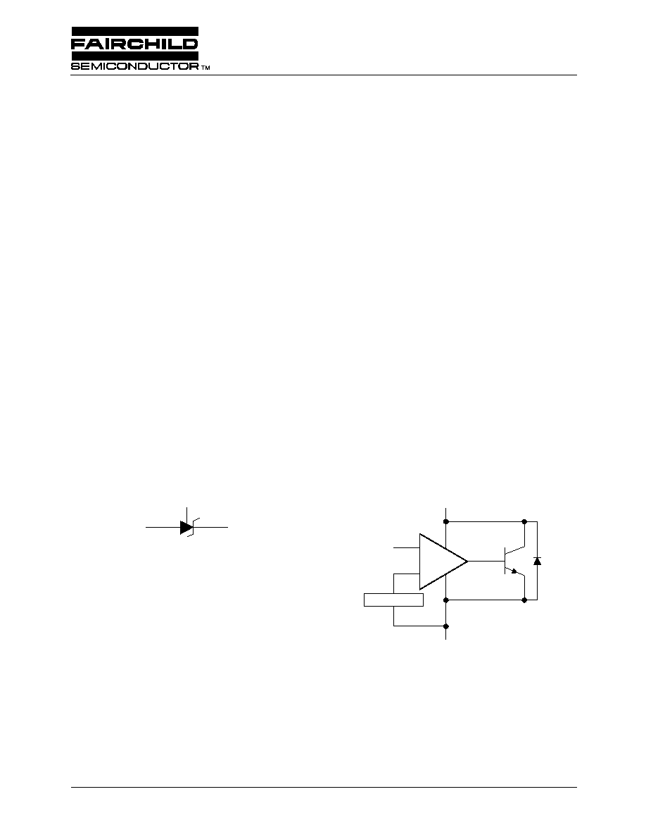
Symbol
Block Diagram
RC0431A (RC431A)
Low-Voltage Adjustable Precision Shunt Regulator
REF
65-431A-01
Anode
Cathode
V
ref
= 1.24V
REF
+
_
CATHODE
ANODE
65-431A-02
RC0431A (RC431A)
PRODUCT SPECIFICATION
2
REV. 1.0.7 8/5/03
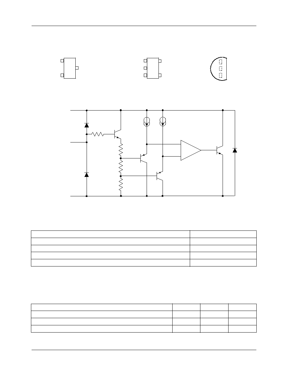
Pin Assignments
Equivalent Schematic
Absolute Maximum Ratings
Ratings are over full operating free-air temperature range unless otherwise noted.
Notes:
1. Functional operation under these conditions is not implied. Permanent damage may occur if the device is subjected to
conditions outside these ratings.
Recommended Operating Conditions
Cathode voltage, V
KA
13.2V
Continuous cathode current I
K
20mA to 20mA
Reference current, I
ref
0.05mA to 3mA
Power dissipation
See Dissipation Rating Table
Storage temperature range
-65
° to 150°C
Parameter
Min.
Max.
Units
Cathode voltage, V
KA
V
REF
12
V
Cathode current, I
K
0.1
15
mA
Operating temperature range in free-air, T
A
0
70
°C
1
2
3
4
5
NC
CATHODE
ANODE
REF
NC
NC = No internal connection
65-431A-03
SOT-23 PACKAGE (5-Lead)
(TOP VIEW)
1
2
3
CATHODE
ANODE
REF
SOT-23 PACKAGE (3-Lead)
(TOP VIEW)
TO-92 PACKAGE
(TOP VIEW)
ANODE
CATHODE
REF
A
REF
CATHODE
65-431A-04
ANODE
PRODUCT SPECIFICATION
RC0431A (RC431A)
REV. 1.0.7 8/5/03
3
Dissipation Rating Table
Electrical Specifications
T
A
= 25
°C (unless otherwise noted), at free-air
Notes:
1. Functional operation under these conditions is not implied. Permanent damage may occur if the device is subjected to
conditions outside these ratings.
2. Full temperature range is 0
°C to 70°C.
3. The deviation parameters V
ref(dev)
and I
ref(dev)
are defined as the differences between the maximum and minimum values
obtained over the rated temperature range. The average full-range temperature coefficient of the reference input voltage,
V
ref
, is defined as:
where
T
A
is the rated operating free-air temperature range of the device.
V
ref
can be positive or negative depending on whether minimum V
ref
or maximum V
ref
, respectively, occurs at the lower
temperature.
4. The dynamic impedance is defined as:
Z
KA
= V
KA
/
I
K
When the device is operating with two external resistors (see Figure 2), the total dynamic impedance of the circuit is given
by:
Package
Power Rating
TA
25°C
Derating Factor
TA
25°C
Power Rating
TA = 70
°C
TO-92
775mW
6.2mW/
O
C
496mW
SOT23-5
150mW
1.2mW/
o
C
96mW
Symbol
Parameters
Conditions
Min.
Typ.
Max.
Units
V
ref
Reference Voltage
V
KA
= V
ref
, T
A
= 25
°C
1.228
1.24
1.252
V
I
K
= 10mA,
T
A
= 0 to 70
°C
1.221
1.259
V
ref (dev)
V
ref
deviation over full temperature
range (see note 2)
V
KA
= V
ref
, I
K
= 10mA,
See note 2 and Figure 1.
4
12
mV
V
ref
V
KA
Ratio of V
ref
change in cathode
voltage change
I
K
= 10mA,
V
KA
= V
ref
to 6V.
See figure 2.
-1.5
-2.7
mV
V
I
ref
Reference terminal current
I
K
= 10mA,
R1 = 10K
, R2 =
See figure 2.
0.15
0.5
µA
I
ref(dev)
I
ref
deviation over full temperature
range (see note 2)
I
K
= 10mA,
R1 = 10K
, R2 =
See note 1 & figure 2.
0.05
0.3
µA
I
K(min)
Minimum cathode current for
regulation
V
KA
= V
ref
See figure 1.
55
80
µA
I
off
Off-state cathode current
V
KA
= 6V, V
ref
= 0
See figure 3.
0.001
0.1
µA
|Z
KA
|
Dynamic impedance (see note 3)
V
KA
= V
ref
, f
1KHz
I
K
= 0.1mA to 15mA,
See figure 1.
0.25
0.4
V
ref
ppm/°C
V
ref dev
(
)
V
ref
T
A
25°C
=
/
{
} 10
6
×
T
A
----------------------------------------------------------------------------------------------
=
Z
KA
V
I
--------
Z
KA
1
R
1
R
2
-------
+
×
=
RC0431A (RC431A)
PRODUCT SPECIFICATION
4
REV. 1.0.7 8/5/03
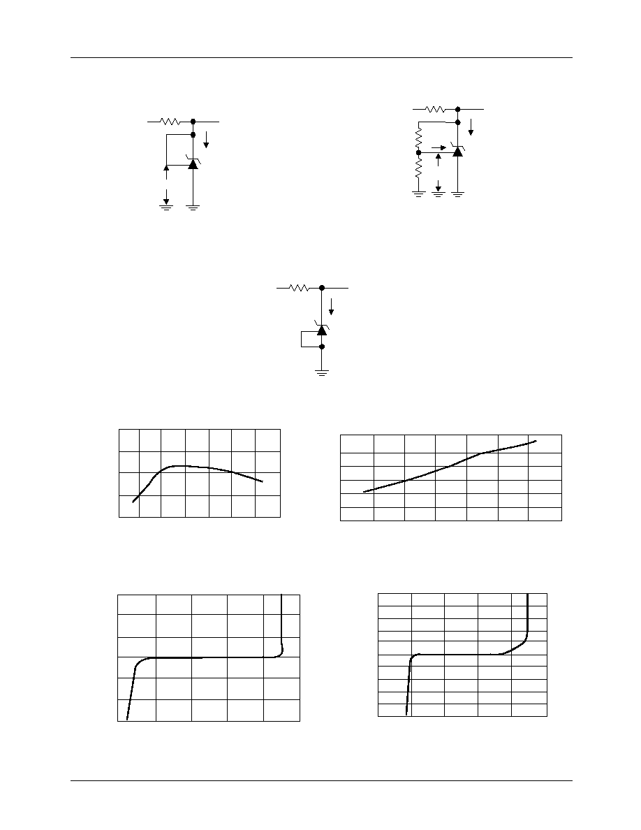
Parameter Measurement Information
Figure 1. Test Circuit for
Figure 2. Test Circuit for
V
KA
= V
REF
, V
OUT
= V
KA
= V
REF
V
KA
> V
REF
, V
OUT
= V
KA
= V
REF
x (1+R1/R2) + I
REF
x R1
Figure 3. Test Circuit for I
OFF
Figure 4. Reference Voltage vs. Junction Temp.
Figure 5. Reference Input Current vs. Junction Temp.
Figure 6. Cathode Current vs. Cathode Voltage
Figure 7. Cathode Current vs. Cathode Voltage
V
OUT
V
65-431A-05
IN
V
ref
I
K
V
OUT
V
IN
V
ref
I
K
R1
R2
I
ref
65-431A-06
V
OUT
V
IN
I
OFF
65-431A-07
1.250
1.246
1.242
1.238
1.230
20
40
20
0
40
60
80
100
Tj--Junction Temp. (
°C)
lk = 10 mA
VrefReference Voltage (V)
250
200
150
100
50
40
20
0
20
40
60
80
100
Tj--Junction Temp. (
°C)
lk = 10 mA, R1 = 10 k
, R2 = infinite
IrefReference Input Current (nA)
15
10
5
0
5
10
15
0.5
-1
0
0.5
1
1.5
V
KA
Cathode Voltage (V)
V
KA
= Vref, T = 25
°C
lkCathode Current (mA)
150
120
90
60
30
0
30
60
90
120
150
0.5
1
0
0.5
1
1.5
V
KA
Cathode Voltage (V)
V
KA
= Vref, T = 25
°C
lkCathode Current (
µ
A)
PRODUCT SPECIFICATION
RC0431A (RC431A)
REV. 1.0.7 8/5/03
5
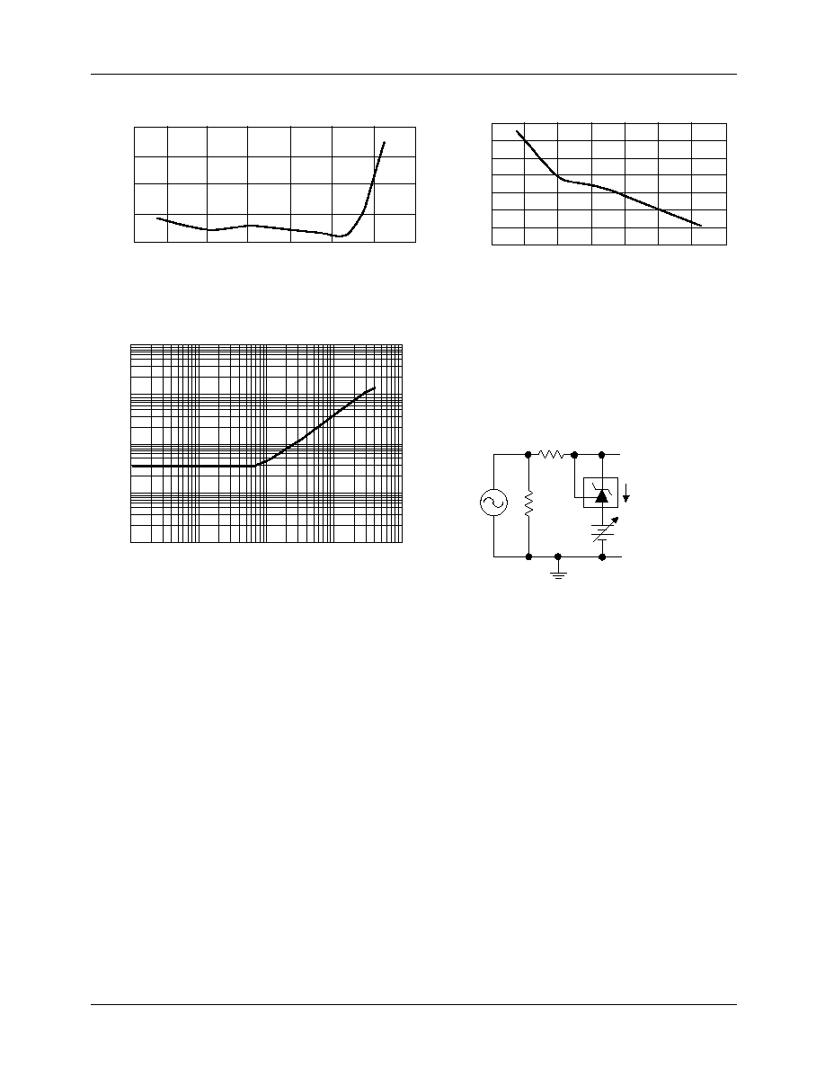
Figure 8. Off-State Cathode Current vs.
Figure 9. Ratio of Delta Reference Voltage
Junction Temperature
to Delta Cathode Voltage vs. Junction Temperature
Figure 10. Reference Impedance vs. Frequency
Figure 11. Test Circuit for Reference Impedance
40.0
30.0
20.0
10.0
0.0
40
0
20
20
40
60
80
100
Tj--Junction Temperature (
°C)
V
KA
= 6V, Vref = 0V
IoffOff State Cathode Current (nA)
1.4
1.2
1.0
0.8
0.6
0.4
0.2
0.0
40
20
0
20
40
60
80
100
Tj--Junction Temperature (
°C)
lk = 10 mA, Del V
KA
= Vref to 6V
Del Vref / Del Vka (mV/V)
100
10
1
0.1
0.01
10000
100000
fFrequency (Hz)
1000000
10000000
1000
|Zka|Reference Impedance (
)
100
100
I
GND
OUTPUT
+
K