Description
Features
Mechanical Dimensions
Electrical Characteristics @ 25
o
C.
Maximum Ratings
Peak Repetitive Reverse Voltage...V
RRM
RMS Reverse Voltage...V
R(rms)
DC Blocking Voltage...V
DC
1N4001GP . . . 7GP Series
Data Sheet
1.0 Amp MEGARECTIFIERS
5 0
100
200
400
600
800
1000
3 5
7 0
140
280
420
560
700
5 0
100
200
400
600
800
1000
............................................. 1.0 ...............................................
............................................. 3 0 ...............................................
............................................. 1.1 ...............................................
Volts
Volts
Volts
Units
1N4001GP . . . 7GP Series
n CAPABILITY OF MEETING
ENVIRONMENTAL STANDARDS
OF MIL-S-19500
Amps
Amps
Volts
µ
Amps
............................................. 3 0 ...............................................
............................................. 5 ...............................................
............................................. 5 0 ...............................................
............................................. 8.0 ...............................................
............................................. 4 5 ...............................................
.........................................
2.0
..........................................
......................................... -65 to 175 ..........................................
µ
Amps
µ
Amps
pF
∞
C / W
µ
S
∞
C
Page 6-4
n HIGH TEMPERATURE METALLURGI-
CALLY BONDED CONSTRUCTION
n SINTERED GLASS CAVITY-FREE
JUNCTION
Average Forward Rectified Current...I
F(av)
Current 3/8" Lead Length @ T
A
= 75
∞
C
Non-Repetitive Peak Forward Surge Current...I
FSM
Ω Sine Wave Superimposed on Rated Load
Forward Voltage @ 1.0A...V
F
Full Load Reverse Current...I
R
(av)
Full Cycle Average @ T
A
= 75
∞
C
DC Reverse Current...I
R
@ Rated DC Blocking Voltage
T
A
= 25
∞
C
T
A
= 125
∞
C
Typical Junction Capacitance...C
J
(Note 1)
Typical Thermal Resistance...R
JA
(Note 2)
Typical Reverse Recovery Time...t
RR
(Note 3)
Operating & Storage Temperature Range...T
J
, T
STRG
1N4001 1N4002 1N4003 1N4004 1N4005 1N4006 1N4007
GP
GP
GP
GP
GP
GP
GP
.205
.160
1.00 Min.
.031 typ.
.080
.107
JEDEC
D0-41
Data Sheet
1.0 Amp MEGARECTIFIERS
1N4001GP . . . 07GP Series
Page 6-5
Ratings at
25 Deg. C ambient
temperature
unless otherwise
specified.
Single Phase Half
Wave, 60 HZ
Resistive or
Inductive Load.
For Capacitive
Load, Derate
Current by 20%.
NOTES: 1. Measured @ 1 MHZ and applied reverse voltage of 4.0V.
2. Thermal Resistance from Junction to Ambient at 3/8" Lead Length, P.C. Board Mounted.
3. Reverse Recovery Condition I
F
= 0.5A, I
R
= 1.0A, I
RR
= 0.25A.
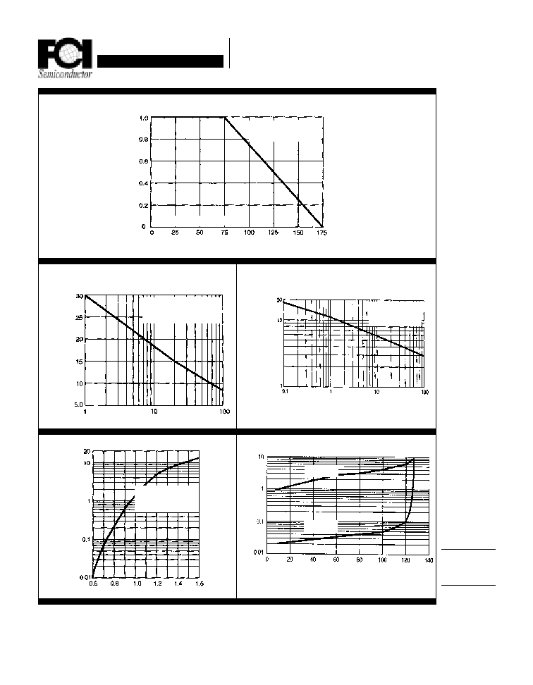
Forward Current Derating Curve
T
A
= Ambient Temperature (
∞
∞
∞
∞
∞
C)
pF
Typical Reverse Characteristics
Non-Repetitive
Peak Forward Surge Current
Amps
Percent of Rated Peak Voltage
Typical Instantaneous Forward Characteristics
Volts
µ
µ
µ
µ
µ
Amps
Typical Junction Capacitance
Reverse Voltage (Volts)
Number of Cycles @ 60 HZ
Amps
Amps
T
J
= 100
∞
∞
∞
∞
∞
C
T
J
= 25
∞
∞
∞
∞
∞
C
60 Hz
RESISTIVE OR
INDUCTIVE LOAD
0.375
(9.5mm) LEAD LENGTH
T
J
= T
J
max.
8.3 mS Single Half Sine Wave
(Jedec Method)
T
J
= 25
∞
∞
∞
∞
∞
C
f = 1.0 MHZ
V
SIG
= 50mVp-p
T
J
= 25
∞
∞
∞
∞
∞
C
Pulse Width = 300
µ
µ
µ
µ
µ
S
1% Duty Cycle