Description
Features
n LOW COST
n HIGH SURGE CAPABILITY
n DIFFUSED JUNCTION
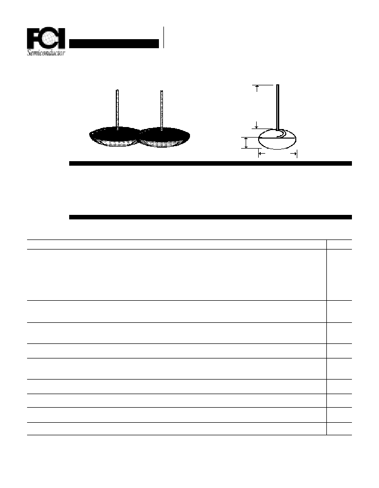
Mechanical Dimensions
n LOW LEAKAGE CURRENT
n HIGH TEMPERATURE CAPABILITY
n MEETS UL SPECIFICATION 94V-0
Electrical Characteristics @ 25
O
C.
Maximum Ratings
Peak Repetitive Reverse Voltage...V
RRM
RMS Reverse Voltage...V
R(rms)
DC Blocking Voltage...V
DC
FDR20/3001 . . . 20/3004 Series
Average Forward Rectified Current...I
F(av)
T
A
= 55
∞
C
(Note 3)
Non-Repetitive Peak Forward Surge Current...I
FSM
@ Rated Current & Temp
Forward Voltage @ 80A...V
F
DC Reverse Current...I
R
@ Rated DC Blocking Voltage, 150
∞
C
Typical Junction Capacitance...C
J
(Note 1)
Typical Thermal Resistance...R
JC
(Note 2)
Typical Reverse Recovery Time...t
RR
Operating & Storage Temperature Range...T
J
, T
STRG
Data Sheet
20 & 30 Amp
AUTOMOTIVE DISH RECTIFIERS
FDR20/3001 . . . 20/3004 Series
Units
FDR20/3001
FDR20/3002
FDR20/3003
FDR20/3004
100
200
300
400
70
140
210
280
100
200
300
400
Volts
Volts
Volts
............................................. 25/35 ...............................................
............................................. 400/500 .................................................
............................................. 1.15 ...............................................
............................................. 2.0 ...............................................
............................................. 250 ...............................................
............................................. 0.8 ...............................................
............................................. 3.0 ...............................................
......................................... -65 to 175 ..........................................
Amps
Amps
Volts
µ
Amps
µ
Amps
pF
∞
C / W
µ
S
∞
C
< ............... 200 ............. >
< ............... 300 ............... >
Page 2-2
1.45/1.65
9.5
2.20
9.25
Data Sheet
20 & 30 Amp
AUTOMOTIVE DISH RECTIFIERS
FDR20/3001 . . . 20/3004 Series
Page 2-3
NOTES: 1. Measured @ 1 MHZ and applied reverse voltage of 4.0V.
2. Thermal Resistance Junction to Ambient, Jedec Method.
3. When Mounted to heat sink, from body.
Ratings at
25 Deg. C ambient
temperature
unless otherwise
specified.
Single Phase Half
Wave, 60 HZ
Resistive or
Inductive Load.
For Capacitive
Load, Derate
Current by 20%.
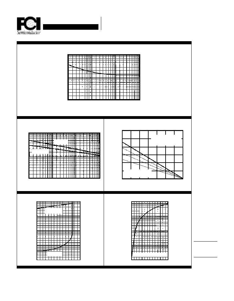
Forward Current Derating Curve
6 0
4 0
2 0
0
2 5 5 0 7 5 100
150
125
175
Lead Temperature (
∞
∞
∞
∞
∞
C)
pF
Single Phase Ω Wave
Res. or Ind. Load
Capacitive Load
I
PK
/AV = 5, 10 & 20
5 0
3 0
1 0
20
10
5
Typical Reverse Characteristics
T
J
= 100
∞
∞
∞
∞
∞
C
T
J
= 25
∞
∞
∞
∞
∞
C
1 0
8 0
4 0
120
1
.1
.01
.001
T
J
= 25
∞
∞
∞
∞
∞
C
T
J
= 150
∞
∞
∞
∞
∞
C
Non-Repetitive
Peak Forward Surge Current
1000
500
200
100
5 0
1 0
.1
1
1 0
100
µ
µ
µ
µ
µ
Amps
Percent of
Rated Peak
Voltage
T
J
= 150
∞
∞
∞
∞
∞
C PW = 300 uS
Typical Instantaneous Forward Characteristics
1000
100
1 0
1
.1
.6 .9 1.1 1.4
2.6
2.3
2.0
Volts
Amps
Typical Junction Capacitance
1000
500
200
100
5 0
1 0
.1
1
1 0
100
Reverse Voltage (Volts)
T
J
= 25
∞
∞
∞
∞
∞
C F = 1 MHZ V
SIG
= 50 Vpp
Number of Cycles @ 60 HZ
Amps
1.7
Amps