Description
Features
Mechanical Dimensions
Maximum Ratings
Peak Repetitive Reverse Voltage...V
RRM
RMS Reverse Voltage...V
R(rms)
DC Blocking Voltage...V
DC
FR150 . . . 1510 Series
Average Forward Rectified Current...I
F(av)
T
A
= 55
∞
C
Non-Repetitive Peak Forward Surge Current...I
FSM
@ Rated Current & Temp
Operating & Storage Temperature Range...T
J
, T
STRG
Maximum Forward Voltage @ 1.5A...V
F
Maximum DC Reverse Current...I
R
@ 25
∞
C
@ Rated DC Blocking Voltage
@ 100
∞
C
Typical Junction Capacitance...C
J
(Note 1)
Maximum Reverse Recovery Time...t
RR
Page 4-8
FR150 . . . 1510 Series
FR150 FR151
FR152 FR154 FR156 FR158 FR1510
50
100
200
400
600
800
1000
35
70
140
280
420
560
700
50
100
200
400
600
800
1000
Data Sheet
1.5 Amp FAST RECOVERY
PLASTIC RECTIFIERS
Units
............................................. 1.5 ...............................................
............................................. 50 ...............................................
........................................ -65 to 150 .........................................
............................................. 1.3 ...............................................
............................................. 5.0 ...............................................
............................................. 100 ...............................................
............................................. 1.5 ...............................................
Volts
Volts
Volts
Amps
Amps
∞
C
Volts
µ
Amps
µ
Amps
pF
ns
n FAST SWITCHING FOR
HIGH EFFICIENCY
n HIGH SURGE CAPABILITY
n 1.5 AMP OPERATION @ T
A
= 55
∞
C, WITH
NO THERMAL RUNAWAY
n MEETS UL SPECIFICATION 94V-0
150
150
150
150
250
500
500
.230
.300
1.00 Min.
.031 typ.
.104
.140
JEDEC
D0-15
Electrical Characteristics
Data Sheet
1.5 Amp FAST RECOVERY
PLASTIC RECTIFIERS
FR150 . . . 1510 Series
Page 4-9
NOTES: 1. Measured @ 1 MHz and applied reverse voltage of 4.0V.
2. Thermal Resistance Junction to Ambient, Jedec Method.
Ratings at
25 Deg. C ambient
temperature
unless otherwise
specified.
Single Phase Half
Wave, 60 Hz
Resistive or
Inductive Load.
For Capacitive
Load, Derate
Current by 20%.
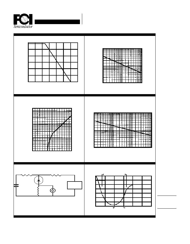
Forward Current Derating Curve
1.5
1.0
.5
0
25
50
75 100
150
125
175
Ambient Temperature (
∞
∞
∞
∞
∞
C)
Average Forward Current (A)
Reverse Recovery Characteristics
Peak Forward Surge Current (A)
Typical Instantaneous Forward Characteristics
Non-Repetitive
Peak Forward Surge Current
Number of Cycles @ 60 Hz
Forward Current (A)
Forward Voltage (V)
Junction Capacitance (pF)
Typical Junction Capacitance
Reverse Voltage (V)
100
50
10
.1
1
1
10
100
10
1
.1
.01
0 .2
1.0 1.2
1.6
Non-Inductive
1
Non-
Inductive
D.U.T
10
Oscilliscope
Note 1
Pulse
Generator
Note 2
(-)
(+)
50
(-)
(+)
25 VDC
Notes: 1. Rise Time = 7 ns Max.
Impedance = 1 megohm, 22 pF
2. Rise Time = 10 ns Max.
Source Impedance = 50 Ohms
Time Base Set @ 50/100ns/cm
+.5A
0A
-.25A
-1.0A
1 cm
t
RR
100
10
1
1
10
100
.4 .6 .8