Description
Features
n HIGH TEMPERATURE METALLURGI-
CALLY BONDED CONSTRUCTION
n SINTERED GLASS CAVITY-FREE
JUNCTION
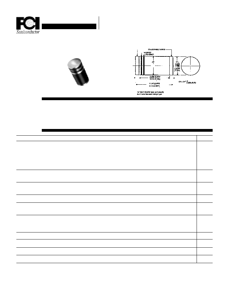
Mechanical Dimensions
Electrical Characteristics @ 25
o
C.
Maximum Ratings
Peak Repetitive Reverse Voltage...V
RRM
RMS Reverse Voltage...V
R(rms)
DC Blocking Voltage...V
DC
GL41A . . . 41M Series
Average Forward Rectified Current...I
F(av)
Current 3/8" Lead Length @ T
A
= 75
∞
C
Non-Repetitive Peak Forward Surge Current...I
FSM
Ω Sine Wave Superimposed on Rated Load
Forward Voltage @ 1.0A...V
F
Full Load Reverse Current...I
R
(av)
Full Cycle Average @ T
A
= 75
∞
C
DC Reverse Current...I
R
@ Rated DC Blocking Voltage
T
A
= 25
∞
C
T
A
= 125
∞
C
Typical Junction Capacitance...C
J
(Note 1)
Typical Thermal Resistance...R
JC
(Note 2)
Operating & Storage Temperature Range...T
J
, T
STRG
Polarity Color Band (2nd Band)
Page 10-10
Data Sheet
1.0 Amp MEGARECTIFIERS
GL41A
GL41B
GL41D
GL41G
GL41J
GL41K
GL41M
5 0
100
200
400
600
800
1000
3 5
7 0
140
280
420
560
700
5 0
100
200
400
600
800
1000
............................................. 1.0 ...............................................
............................................. 3 0 ...............................................
< ............................. 1.1 ........................... > < .... 1.2 .... >
Volts
Volts
Volts
Units
GL41A . . . 41M Series
n 1.0 AMP OPERATION @ T
A
= 55
∞
C, WITH
NO THERMAL RUNAWAY
n TYPICAL I
R
< 0.1
µ
Amp
Amps
Amps
Volts
µ
Amps
............................................. 3 0 ...............................................
............................................. 5.0 ...............................................
............................................. 5 0 ...............................................
............................................. 8.0 ...............................................
............................................. 7 5 ...............................................
......................................... -65 to 175 ..........................................
µ
Amps
µ
Amps
pF
∞
C / W
∞
C
Gray
Red
Orange Yellow Green
Blue
Violet
Dimensions in inches
and (millimeters)

Data Sheet
1.0 Amp MEGARECTIFIERS
GL41A . . . 41M Series
Page 10-11
NOTES: 1. Measured @ 1 MHZ and applied reverse voltage of 4.0V.
2. Thermal Resistance from Junction to Ambient, 6.0mm' copper
pad to each terminal.
Ratings at
25 Deg. C ambient
temperature
unless otherwise
specified.
Single Phase Half
Wave, 60 HZ
Resistive or
Inductive Load.
For Capacitive
Load, Derate
Current by 20%.
Forward Current Derating Curve
Terminal Temperature (
∞
∞
∞
∞
∞
C)
pF
Typical Reverse Characteristics
Non-Repetitive
Peak Forward Surge Current
µ
µ
µ
µ
µ
Amps
Percent of Rated Peak Voltage
Typical Instantaneous Forward Characteristics
Volts
Amps
Typical Junction Capacitance
Reverse Voltage (Volts)
Number of Cycles @ 60 HZ
Amps
Amps