Description
Features
n LOW COST
n HIGH SURGE CAPABILITY
n DIFFUSED JUNCTION
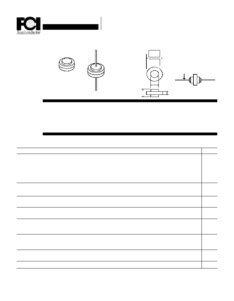
Mechanical Dimensions
n LOW LEAKAGE CURRENT
n VERY FAST RECOVERY TIME (t
RR
)
n MEETS UL SPECIFICATION 94V-0
Electrical Characteristics @ 25
o
C.
Maximum Ratings
Peak Repetitive Reverse Voltage...V
RRM
RMS Reverse Voltage...V
R(rms)
DC Blocking Voltage...V
DC
VFR2501 . . . 2510 Series
Average Forward Rectified Current...I
F(av)
T
A
= 55
∞
C
(Note 3)
Repetitive Peak Forward Surge Current...I
FM
@ Rated V
R,
Square Wave, 20 KHZ, T
C
= 150
∞
C
Non-Repetitive Peak Forward Surge Current...I
FSM
@ Rated Load Conditions, Ω Wave, Single Phase, 60 HZ
Forward Voltage...V
F
@ I
F
= 15 Amps, PW = 300
µ
S, T
C
= 150
∞
C
T
C
= 25
∞
C
DC Reverse Current...I
R
@ Rated DC Blocking Voltage T
C
= 150
∞
C
T
C
= 25
∞
C
Typical Reverse Recovery Time...t
RR
I
F
= 1.0 Amp, di/dt = 50 Amps/
µ
S
Operating & Storage Temperature Range...T
J
, T
STRG
Page 2-8
VFR2501 . . . 2510 Series
Data Sheet
25 Amp PLASTIC FAST RECOVERY
SILICON AUTOMOTIVE RECTIFIERS
VFR2501 VFR2502 VFR2503 VFR2504 VFR2506 VFR2508 VFR2510
100
200
300
400
600
800
1000
70
140
210
280
420
560
700
100
200
300
400
600
800
1000
Units
............................................. 25 ...............................................
............................................. 30 ...............................................
............................................. 300 ...............................................
............................................. 500 ...............................................
............................................. 10 ...............................................
......................................... -65 to 175 ..........................................
Volts
Volts
Volts
Amps
Amps
Amps
Volts
Volts
µ
Amps
µ
Amps
nS
∞
C
< ..................... 0.880 ................. > < ...... 1.12 ...... > <1.34 >
< ..................... 0.975 ................. > < ...... 1.3 ...... > <1.5 >
< ............... 150 ............. >
< ............... 200 ............... >
FR2500
.395
FR2500S
.337
.220
.242
.175
Leads 1.00 typ. .05 Dia.
Data Sheet
25 Amp PLASTIC FAST RECOVERY
SILICON AUTOMOTIVE RECTIFIERS
VFR2501 . . . 2510 Series
Page 2-9
NOTES: 1. Measured @ 1 MHZ and applied reverse voltage of 4.0V.
2. Thermal Resistance Junction to Ambient, Jedec Method.
3. When Mounted to heat sink, from body.
Ratings at
25 Deg. C ambient
temperature
unless otherwise
specified.
Single Phase Half
Wave, 60 HZ
Resistive or
Inductive Load.
For Capacitive
Load, Derate
Current by 20%.
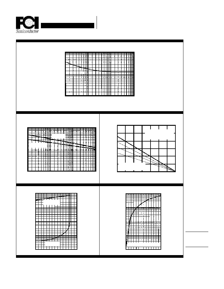
Forward Current Derating Curve
60
40
20
0
25 50 75 100
150
125
175
Lead Temperature (
∞
∞
∞
∞
∞
C)
pF
Single Phase Ω Wave
Res. or Ind. Load
Capacitive Load
I
PK
/AV = 5, 10 & 20
50
30
10
20
10
5
Typical Reverse Characteristics
T
J
= 100
∞
∞
∞
∞
∞
C
T
J
= 25
∞
∞
∞
∞
∞
C
10
80
40
120
1
.1
.01
.001
T
J
= 25
∞
∞
∞
∞
∞
C
T
J
= 150
∞
∞
∞
∞
∞
C
Non-Repetitive
Peak Forward Surge Current
1000
500
200
100
50
10
.1
1
10
100
µ
µ
µ
µ
µ
Amps
Percent of
Rated Peak
Voltage
T
J
= 150
∞
∞
∞
∞
∞
C PW = 300 uS
Typical Instantaneous Forward Characteristics
1000
100
10
1
.1
.6 .9 1.1 1.4
2.6
2.3
2.0
Volts
Amps
Typical Junction Capacitance
1000
500
200
100
50
10
.1
1
10
100
Reverse Voltage (Volts)
T
J
= 25
∞
∞
∞
∞
∞
C F = 1 MHZ V
SIG
= 50 Vpp
Number of Cycles @ 60 HZ
Amps
1.7
Amps