
CONFIDENTIAL
Microelectronics, Inc.
EK7011TCB-1801
160 Output Segment & Common
LCD Driver
Eureka
6F, NO.12, INNOVATION 1
ST
. RD.,
SCIENCE-BASED INDUSTRIAL PARK, HSIN-CHU
CITY, TAIWAN, R.O.C.
TEL
886-3-5799255
FAX
886-3-5799253
http://www.eureka.com.tw
CONFIDENTIAL
EUREKA
EK7011TCB-1801
1 Rev 1.2 Oct.22.2001
Description
The EK7011 is a 160 output segment/common LCD
driver adaptable to drive a large scale dot matrix panel.
It uses the Tape Carrier Package(TCP) to greatly
reduce the size of the LCD module. EK7011 consumes
very little power. Large LCD panels can be assembled
by cascading EK7011s. In Segment Mode, the input
data can be either 4-bit parallel or 8-bit parallel, selected
by the Mode Select pin (MD).
160 Output Segment/Common LCD Driver
Features
l
CMOS process
l
Logic power supply : 2.5V to 5.5V
l
Low power consumption
l
160 LCD display output
l
Supply voltage for LCD driver :15 to 40V
l
Package : TCP, COG available
Features in Segment mode
l
Shift clock frequency : 14MHz max. at V
DD
=5V
l
4bit/8bit parallel input
l
Automatic transfer of enable signal
l
Automatic counting in the chip select mode. The
internal clock stoped by automatically counting
160 of input data.
Features in Common mode
l
Shift clock frequency : 4MHz max. at V
DD
=5V
l
Built-in 160-bit bidirectional shift register
l
Single mode (160-bit shift register) or Dual Mode
(two 80-bit shift registers) with these options:
1. Y1 Y160 Single mode
2. Y160 Y1 Single mode
3. Y1 Y80, Y81 Y160 Dual mode
4. Y160 Y81, Y80 Y1 Dual mode
Y
1
Y
2
Y
3
Y
4
Y
1 60
X C K
L/R
M D
S /C
V
1 2R
V
0 R
V
1 2L
V
0 L
D I
0
D I
7
F R
D IS P O F F
E IO
1
LP
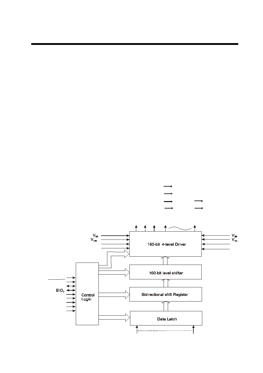
Block Diagram
Fig.1

CONFIDENTIAL
EUREKA
EK7011TCB-1801
2 Rev 1.2 Oct.22.2001
Pin Configuration
Fig.2
V
0
L
1
2L
4
3L
S
S
D
D
2
0
1
2
3
4
5
6
7
1
S
S
4
3R
1
2R
0
R
V
V
V
L/
R
V
S
/C
E
IO
D
I
D
I
D
I
D
I
D
I
D
I
D
I
D
I
X
C
K
D
IS
P
O
F
F
LP
E
IO
F
R
M
D
V
V
V
V
1 6 9 . . . . . . . . . . . . . . . . . . . . . . . . . . . . . . . . . . . . . . . . . . . . . . . . . . . . . . . . . . . . . . . . . . . . .. . . . . . . . . . . . . . . . . . . . . . . . . . . . . . . . . . . . . 1 9 4
1 6 8 . . . . . . . . . . . . . . . . . . .. . . . . . . . . . . . . . . . . . . . . . . . . . . . . . . . . . . . . . . . . . . . . . . . . . . . . . . . . . . . . . . . . . . . . . . . . . . . . . . . . . . . . . . . . . . . . . . . . .. . . . . .. . . . . . . . . . . . . 1
Y
Y
Y
1
6
0
1
5
9
1
5
8
Y
Y
Y
3
2
1
C h ip S u r f a c e
D
u
m
m
y
D
u
m
m
y
D
u
m
m
y
D
u
m
m
y
D
u
m
m
y
D
u
m
m
y
D
u
m
m
y
D
u
m
m
y

CONFIDENTIAL
EUREKA
EK7011TCB-1801
3 Rev 1.2 Oct.22.2001
Pin Designations
Tab.1
.
o
N
n
i
P
l
o
b
m
y
S
O
/I
n
o
it
a
n
g
is
e
D
4
6
1
o
t
5
Y
1
Y
-
0
6
1
O
t
u
p
t
u
o
D
C
L
4
9
1
,
9
6
1
V
L
0
V
,
R
0
-
l
e
v
e
l
r
e
v
ir
d
D
C
L
r
o
f
y
l
p
p
u
s
r
e
w
o
P
3
9
1
,
0
7
1
V
L
2
1
V
,
R
2
1
-
l
e
v
e
l
r
e
v
ir
d
D
C
L
r
o
f
y
l
p
p
u
s
r
e
w
o
P
2
9
1
,
1
7
1
V
L
3
4
V
,
R
3
4
-
l
e
v
e
l
r
e
v
ir
d
D
C
L
r
o
f
y
l
p
p
u
s
r
e
w
o
P
3
7
1
R
/
L
I
n
o
it
c
e
l
e
s
n
o
it
c
e
ri
d
tf
i
h
s
a
t
a
d
y
a
l
p
s
i
D
4
7
1
D
D
V
-
)
V
5
.
5
+
o
t
5
.
2
+
(t
i
u
c
ri
c
c
i
g
o
l
r
o
f
y
l
p
p
u
s
r
e
w
o
P
5
7
1
C
/
S
I
n
o
it
c
e
l
e
s
e
d
o
m
n
o
m
m
o
c
/
e
d
o
m
t
n
e
m
g
e
S
6
7
1
O
I
E
2
O
/I
r
e
ts
i
g
e
r
tf
i
h
s
f
o
a
t
a
d
r
o
t
c
e
l
e
s
p
i
h
c
r
o
f
t
u
p
t
u
o
/t
u
p
n
I
3
8
1
o
t
7
7
1
I
D
~
0
I
D
6
I
e
d
o
m
t
n
e
m
g
e
s
n
i
a
t
a
d
y
a
l
p
s
i
d
f
o
t
u
p
n
I
4
8
1
I
D
7
I
t
u
p
n
i
a
t
a
d
e
d
o
m
l
a
u
D
r
o
,
e
d
o
m
t
n
e
m
g
e
S
n
i
a
t
a
d
y
a
l
p
s
i
d
f
o
t
u
p
n
I
e
d
o
m
n
o
m
m
o
c
n
i
5
8
1
K
C
X
I
e
d
o
m
t
n
e
m
g
e
s
n
i
t
u
p
n
i
k
c
o
l
c
tf
i
h
s
a
t
a
d
y
a
l
p
s
i
D
6
8
1
F
F
O
P
S
I
D
I
l
e
v
e
l
t
u
p
t
u
o
t
c
e
l
e
s
e
d
o
t
t
u
p
n
i
n
i
p
l
o
rt
n
o
C
7
8
1
P
L
I
e
d
o
m
t
n
e
m
g
e
s
n
i
t
u
p
n
i
e
s
l
u
p
h
c
t
a
L
e
d
o
m
n
o
m
m
o
c
n
i
r
e
ts
i
g
e
r
tf
i
h
s
r
o
f
t
u
p
n
i
k
c
o
l
c
tf
i
h
S
8
8
1
O
I
E
1
O
/I
r
e
ts
i
g
e
r
tf
i
h
s
f
o
a
t
a
d
r
o
t
c
e
l
e
s
p
i
h
c
r
o
f
t
u
p
t
u
o
/t
u
p
n
I
9
8
1
R
F
I
m
r
o
f
e
v
a
w
r
e
v
ir
d
D
C
L
r
o
f
t
u
p
n
i
l
a
n
g
is
g
n
it
r
e
v
n
o
c
-
C
A
0
9
1
D
M
I
n
o
it
c
e
l
e
s
e
d
o
M
1
9
1
,
2
7
1
S
S
V
-
d
n
u
o
r
G
8
6
1
~
5
6
1
,
4
~
1
y
m
m
u
D
-
S
D
A
P
y
m
m
u
D
CONFIDENTIAL
EUREKA
EK7011TCB-1801
4 Rev 1.2 Oct.22.2001
Input/Output Circuit
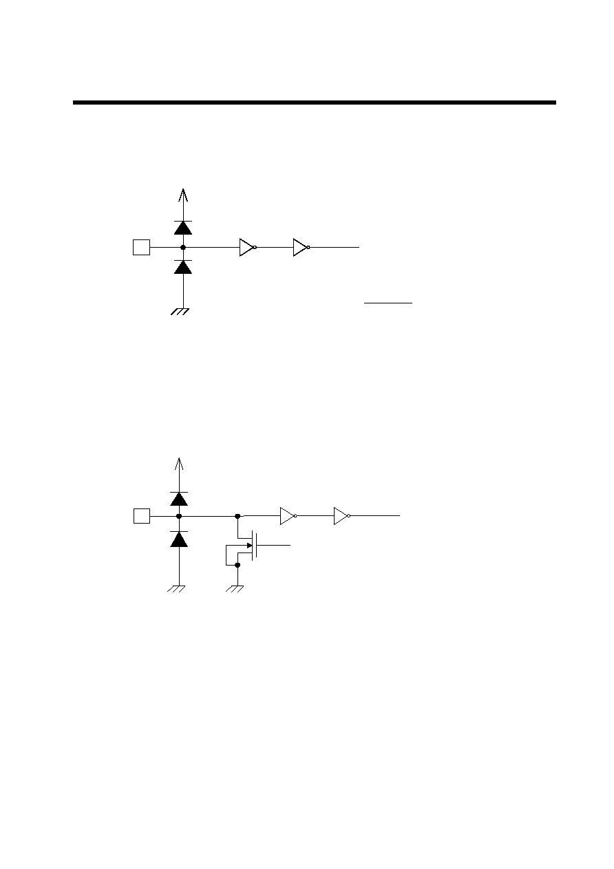
Fig.3 Input Circuit(1)
Fig.4 Input Circuit(2)
I
Input Signal
V
,,
V
55
(Applicable pins)
L/R, S/C, DI
~ DI
%
DISPOFF, LP, FR, MD
I
Input Signal
V
,,
V
55
(Applicable pins)
DI
%
, XCK
V
55
Control Signal
CONFIDENTIAL
EUREKA
EK7011TCB-1801
5 Rev 1.2 Oct.22.2001
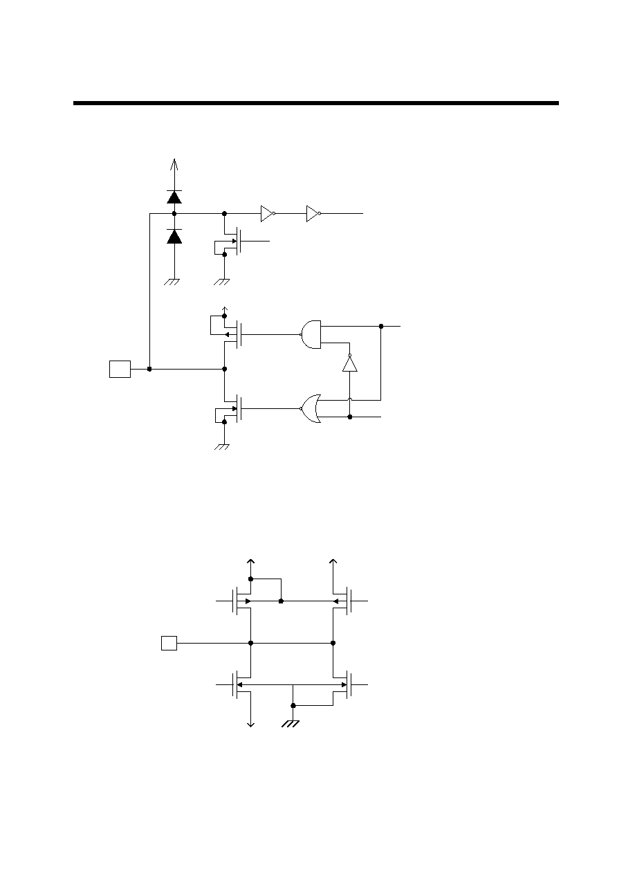
Fig.5 Input/Output Circuit
Fig.6 LCD Driver Output Circuit
I/O
Input Signal
V
,,
V
55
(Applicable pins)
EIO
, EIO
V
55
Control Signal
Output Signal
Control Signal
V
,,
O
Control Signal 3
Control Signal 1
Control Signal 2
Control Signal 4
V
55
V
"!
V
V
(Applicable pins)
Y
to Y
$

CONFIDENTIAL
EUREKA
EK7011TCB-1801
6 Rev 1.2 Oct.22.2001
Pin Functions
(Segment mode)
l
l
l
l
l
l
l
l
l
l
l
l
l
l
l
Tab.2
l
Symbol
Function
V
DD
Logic circuit power supply +2.5 to +5.5 V
V
SS
Ground pin
V
0R
, V
0L
V
12R
, V
12L
V
43R
, V
43L
Power supply for LCD driver voltage level
Normally, the bias voltage used is set by a resistor divider.
Ensure that voltages are set such that Vss<V
43
<V
12
<V
0
.
V
iR
and V
iL
(i=0, 12, 43) should be externally connected to reduce the difference between
the waveforms of the output pins Y
1
~Y
160
.
DI
0~
DI
7
Input for display data
In 4-bit parallel input mode, input data into the 4 pins DI
0~
DI
3
.
Connect DI
4~
DI
7
to V
SS
or V
DD
.
In 8-bit parallel input mode, input data into the 8 pins DI
0~
DI
7
.
XCK
Input clock pin for displaying data
Data is read on the falling edge of the clock pulse.
LP
Latch pulse input for displaying data
Data is latched on the falling edge of the clock pulse.
L/R
Direction selection for reading display data
When set to V
SS
, data is read sequentially from Y
160
to Y
1
.
When set to V
DD
, data is read sequentially from Y
1
to Y
160
.
DISPOFF
Control input to deselect output level
The input signal is level-shifted from logic voltage level to LCD drive voltage level, and
controls LCD drive circuit.
When set to Vss level "L", the LCD driver output pins (Y
1~
Y
160
) are set to level Vss .
While set to "L", the contents of the line latch are cleared, but read the display data in the
data latch regardless of condition of DISPOFF. When the DISPOFF function is cancelled, the
driver outputs deselect level (V
12
or V
43
),then outputs the contents of the data latch on the
next falling edge of the LP. At that time, if DISPOFF removal time does not meet the
conditions shown in Tab.15, it can not output the reading data correctly.
FR
AC signal for LCD driver output level
The input signal is level-shifted from logic voltage level to LCD drive voltage level, and
controls LCD drive circuit.
Normally, inputs a frame inversion signal.
The LCD driver output voltage level of output pin can be setted using the line latch output
signal and the FR signal.
Truth table is shown on Tab.6 & Tab.7.

CONFIDENTIAL
EUREKA
EK7011TCB-1801
7 Rev 1.2 Oct.22.2001
Pin Functions
(Segment mode)
l
l
l
Tab.3
l
l
l
l
l
l
Symbol
Function
MD
Mode selection
When set to V
SS
level "L", 4-bit parallel input mode is selected.
When set to V
DD
level "H", 8-bit parallel input mode is selected.
The relationship between the display data and driver output pins is shown on Tab.8 & Tab.9.
S/C
Segment mode/common mode selection pin
When set to V
DD
, segment input mode is set.
EIO
1
EIO
2
Input/Output for chip selection
When L/R input is at V
SS
level "L", EIO
1
is set for output, and EIO
2
is set for input.
When L/R input is at V
DD
level "H", EIO
1
is set for input, and EIO
2
is set for output.
During output, set to "H" while LP*XCK is "H" and after 160-bit data have been read, set
to "L" for one cycle (from falling edge of XCK to next falling edge of XCK), after which it
returns to "H".
During input, after the LP signal is input, the chip is selected while EI is set to "L". After
160-bits of data have been read, the chip is deselected.
Y
1
-Y
160
LCD driver output
Corresponding directly to each bit of the data latch, one level(V
0
, V
12
, V
43
, or Vss) is selected
for output.
Truth table values is shown on Tab.6 & Tab.7.
l

CONFIDENTIAL
EUREKA
EK7011TCB-1801
8 Rev 1.2 Oct.22.2001
(Common mode)
l
o
b
m
y
S
n
o
it
c
n
u
F
V
D
D
.
V
5
.
5
+
o
t
5
.
2
+
o
t
st
c
e
n
n
o
c
n
i
p
y
l
p
p
u
s
r
e
w
o
p
ti
u
c
ri
c
c
i
g
o
L
V
S
S
.
n
i
p
d
n
u
o
r
G
V
R
0
V
,
L
0
V
R
2
1
V
,
L
2
1
V
R
3
4
V
,
L
3
4
s
a
i
b
e
g
at
l
o
v
r
e
v
ir
d
D
C
L
r
o
f
n
i
p
y
l
p
p
u
s
r
e
w
o
P
.r
e
d
i
v
i
d
r
o
ts
is
e
r
a
y
b
t
e
s
si
d
e
s
u
e
g
at
l
o
v
s
a
i
b
e
h
t
,y
ll
a
m
r
o
N
V
t
a
h
t
h
c
u
s
t
e
s
e
r
a
s
e
g
at
l
o
v
t
a
h
t
e
r
u
s
n
E
S
S
V
<
3
4
V
<
2
1
V
<
.
0
n
e
e
w
t
e
b
e
c
n
e
r
e
ff
i
d
e
h
t
e
c
u
d
e
r
o
t
d
et
c
e
n
n
o
c
y
ll
a
n
r
et
x
e
e
b
d
l
u
o
h
s
)
3
4
,
2
1
,
0
=
i(
L
i
V
d
n
a
R
i
V
.
0
6
1
Y
~
1
Y
s
n
i
p
t
u
p
t
u
o
e
h
t
f
o
s
m
r
o
f
e
v
a
w
e
h
t
O
I
E
1
.t
u
p
t
u
o
/t
u
p
n
i
r
et
si
g
e
r
tf
i
h
s
l
a
n
o
it
c
e
ri
d
i
B
V
t
a
si
R
/
L
n
e
h
w
t
u
p
n
i
,"
L
"
l
e
v
e
l
s
s
V
t
a
t
e
s
si
R
/
L
n
e
h
w
t
u
p
t
u
O
D
D
."
H
"
l
e
v
e
l
O
I
E
n
e
h
W
1
.n
w
o
d
-l
l
u
p
e
b
ll
i
w
ti
,n
i
p
t
u
p
n
i
s
a
d
e
s
u
si
O
I
E
n
e
h
W
1
.n
w
o
d
-l
l
u
p
e
b
t
o
n
ll
i
w
ti
,n
i
p
t
u
p
t
u
o
s
a
d
e
s
u
si
O
I
E
2
.t
u
p
t
u
o
/t
u
p
n
i
r
et
si
g
e
r
tf
i
h
s
l
a
n
o
it
c
e
ri
d
i
B
V
t
a
t
e
s
si
R
/
L
n
e
h
w
t
u
p
n
I
S
S
V
t
a
si
R
/
L
n
e
h
w
t
u
p
t
u
o
,"
L
"
l
e
v
e
l
D
D
."
H
"
l
e
v
e
l
O
I
E
n
e
h
W
2
..
n
w
o
d
-l
l
u
p
e
b
ll
i
w
ti
,t
u
p
n
i
s
a
d
e
s
u
si
O
I
E
n
e
h
W
2
.n
w
o
d
-l
l
u
p
e
b
t
o
n
ll
i
w
ti
,t
u
p
t
u
o
s
a
d
e
s
u
si
P
L
t
u
p
n
i
e
sl
u
p
k
c
o
l
c
r
et
si
g
e
r
tf
i
h
s
l
a
n
o
it
c
e
ri
d
i
B
.e
sl
u
p
k
c
o
l
c
e
h
t
f
o
e
g
d
e
g
n
il
l
a
f
e
h
t
n
o
d
et
fi
h
s
si
at
a
D
R
/
L
n
o
it
c
e
l
e
s
n
o
it
c
e
ri
d
tf
i
h
s
r
et
si
g
e
r
tf
i
h
s
l
a
n
o
it
c
e
ri
d
i
B
V
o
t
t
e
s
n
e
h
W
S
S
Y
m
o
rf
d
et
fi
h
s
si
at
a
d
,
0
6
1
Y
o
t
1
.
V
o
t
t
e
s
n
e
h
W
D
D
Y
m
o
rf
d
et
fi
h
s
si
at
a
d
,
1
Y
o
t
0
6
1
.
F
F
O
P
S
I
D
l
e
v
e
l
t
u
p
t
u
o
t
c
e
l
e
s
e
d
o
t
n
i
p
t
u
p
n
i
l
o
rt
n
o
C
d
n
a
,l
e
v
e
l
e
g
at
l
o
v
e
v
ir
d
D
C
L
o
t
l
e
v
e
l
e
g
at
l
o
v
c
i
g
o
l
m
o
rf
d
et
fi
h
s
-l
e
v
e
l
si
l
a
n
g
is
t
u
p
n
i
e
h
T
.t
i
u
c
ri
c
e
v
ir
d
D
C
L
sl
o
rt
n
o
c
Y
(
s
n
i
p
t
u
p
t
u
o
r
e
v
ir
d
D
C
L
e
h
t
,"
L
"
o
t
t
e
s
n
e
h
W
1
Y
-
0
6
1
V
l
e
v
e
l
o
t
t
e
s
e
r
a
)
S
S
.
n
o
it
c
n
u
f
F
F
O
P
S
I
D
e
h
t
n
e
h
W
.
d
e
r
a
e
l
c
e
r
a
r
et
si
s
e
r
tf
i
h
s
e
h
t
f
o
st
n
et
n
o
c
e
h
t
,"
L
"
o
t
t
e
s
e
li
h
W
V
(
l
e
v
e
l
t
c
e
l
e
s
e
d
st
u
p
t
u
o
r
e
v
ir
d
e
h
t
,
d
e
ll
e
c
n
a
c
si
2
1
o
V
r
3
4
e
h
t
n
o
d
a
e
r
si
at
a
d
tf
i
h
s
e
h
t
d
n
a
.)
e
h
t
t
e
e
m
t
o
n
s
e
o
d
e
m
it
l
a
v
o
m
e
r
F
F
O
P
S
I
D
e
h
t
fi
,
e
m
it
t
a
h
t
t
A
.
P
L
e
h
t
f
o
e
g
d
e
g
n
il
l
a
f
.y
lt
c
e
rr
o
c
d
a
e
r
t
o
n
si
at
a
d
tf
i
h
s
e
h
t
n
e
h
t
,
5
1
.g
i
F
n
i
n
w
o
h
s
s
n
o
it
i
d
n
o
c
R
F
l
e
v
e
l
t
u
p
t
u
o
r
e
v
ir
d
D
C
L
r
o
f
t
u
p
n
i
l
a
n
g
is
C
A
d
n
a
,l
e
v
e
l
e
g
at
l
o
v
e
v
ir
d
D
C
L
o
t
l
e
v
e
l
e
g
at
l
o
v
c
i
g
o
l
m
o
rf
d
et
fi
h
s
-l
e
v
e
l
si
l
a
n
g
is
t
u
p
n
i
e
h
T
.t
i
u
c
ri
c
e
v
ir
d
D
C
L
sl
o
rt
n
o
c
l
a
n
g
is
t
u
p
t
u
o
r
et
si
g
e
r
tf
i
h
s
e
h
t
g
n
is
u
y
b
t
e
s
e
b
n
a
c
l
e
v
e
l
e
g
at
l
o
v
t
u
p
t
u
o
r
e
v
ir
d
D
C
L
e
h
T
.l
a
n
g
is
R
F
e
h
t
d
n
a
.
7
b
a
T
&
6
b
a
T
n
o
n
w
o
h
s
si
e
l
b
at
h
t
u
r
T
Pin Functions
l
l
l
l
l
l
l
l
l
l
l
l
l
l
l
l
Tab.4
l
l

CONFIDENTIAL
EUREKA
EK7011TCB-1801
9 Rev 1.2 Oct.22.2001
Pin Functions
(Common mode)
l
o
b
m
y
S
n
o
it
c
n
u
F
D
M
n
o
it
c
e
l
e
s
e
d
o
M
V
o
t
t
e
s
n
e
h
w
,
d
e
t
c
e
l
e
s
s
i
n
o
it
a
r
e
p
o
e
d
o
M
e
l
g
n
i
S
,"
L
"
l
e
v
e
l
s
s
V
o
t
t
e
s
n
e
h
W
D
D
,"
H
"
l
e
v
e
l
.
d
e
t
c
e
l
e
s
s
i
n
o
it
a
r
e
p
o
e
d
o
M
l
a
u
D
I
D
7
t
u
p
n
i
a
t
a
d
e
d
o
M
l
a
u
D
g
n
it
r
a
t
s
t
u
p
n
i
e
b
n
a
c
a
t
a
d
,r
e
t
s
i
g
e
r
tf
i
h
s
a
t
a
d
e
h
t
f
o
n
o
it
c
e
ri
d
tf
i
h
s
a
t
a
d
e
h
t
o
t
g
n
i
d
r
o
c
c
A
.t
i
b
h
t
1
8
e
h
t
m
o
rf
I
D
,
e
d
o
M
l
a
u
D
s
a
d
e
s
u
s
i
p
i
h
c
e
h
t
n
e
h
W
7
.
n
w
o
d
-l
l
u
p
e
b
ll
i
w
I
D
,
e
d
o
M
e
l
g
n
i
S
s
a
d
e
s
u
s
i
p
i
h
c
e
h
t
n
e
h
W
7
.
n
w
o
d
-l
l
u
p
e
b
t
o
n
ll
i
w
C
/
S
n
o
it
c
e
l
e
s
e
d
o
m
n
o
m
m
o
c
/
e
d
o
m
t
n
e
m
g
e
S
V
o
t
t
e
s
n
e
h
W
S
S
.
d
e
tt
e
s
s
i
e
d
o
M
n
o
m
m
o
C
,"
L
"
l
e
v
e
l
I
D
0
I
D
~
6
d
e
s
u
t
o
N
I
D
t
c
e
n
n
o
C
0
I
D
~
6
V
o
t
S
S
V
r
o
D
D
.
g
n
it
a
o
lf
g
n
i
d
i
o
v
A
.
K
C
X
d
e
s
u
t
o
N
.
n
e
p
o
r
o
s
s
V
o
t
m
e
h
t
t
c
e
n
n
o
c
o
s
,
e
d
o
m
n
o
m
m
o
c
n
i
n
w
o
d
-l
l
u
p
s
i
K
C
X
Y
1
Y
~
0
6
1
t
u
p
t
u
o
r
e
v
ir
d
D
C
L
V
(
l
e
v
e
l
e
n
o
,r
e
t
s
i
g
e
r
tf
i
h
s
e
h
t
f
o
ti
b
h
c
a
e
o
t
y
lt
c
e
ri
d
g
n
i
d
n
o
p
s
e
r
r
o
C
0
V
,
2
1
V
,
3
4
V
r
o
,
S
S
s
i)
.
d
e
t
c
e
l
e
s
.
7
.
b
a
T
&
6
.
b
a
T
n
o
n
w
o
h
s
s
i
e
l
b
a
t
h
t
u
r
T
l
l
l
l
l
l
Tab.5
l
l
l

CONFIDENTIAL
EUREKA
EK7011TCB-1801
10 Rev 1.2 Oct.22.2001
Functional Operations
Truth Table
(Segment Mode)
R
F
a
t
a
D
h
c
t
a
L
F
F
O
P
S
I
D
Y
(l
e
v
e
L
e
g
a
tl
o
V
t
u
p
t
u
O
r
e
v
i
r
D
1
Y
-
0
6
1
)
L
L
H
V
3
4
L
H
H
V
S
S
H
L
H
V
2
1
H
H
H
V
0
X
X
L
V
S
S
Here, Vss
<
V
43
<
V
12
<
V
0
, H
:
V
DD
(+2.5 to +5.5V), L
:
V
SS
(0 V)
X
:
Dont care
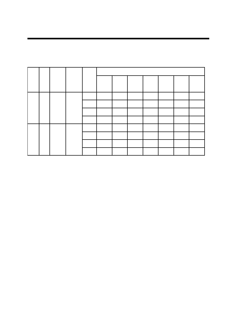
Tab.6
(Common Mode)
R
F
a
t
a
D
h
c
t
a
L
F
F
O
P
S
I
D
Y
(l
e
v
e
L
e
g
a
tl
o
V
t
u
p
t
u
O
r
e
v
i
r
D
1
Y
-
0
6
1
)
L
L
H
V
3
4
L
H
H
V
0
H
L
H
V
2
1
H
H
H
V
S
S
X
X
L
V
S
S
Here, V
SS
<
V
43
<
V
12
<
V
0
, H
:
V
DD
(+2.5 to +5.5V), L
:
V
SS
(0 V)
X
:
Dont care
Note
:
There have two kinds of power supply (logic level voltage, LCD drive voltage) for LCD
driver.
Supply proper voltage according to each power pin specification.
Dont care means that should be connected to H or L. Do not leave them open.
Tab.7
CONFIDENTIAL
EUREKA
EK7011TCB-1801
11 Rev 1.2 Oct.22.2001
Relationship between the Display Data and Driver Output pins
(Segment Mode)
(a)4-bit Parallel Mode
D
M
R
/
L
O
I
E
1
O
I
E
2
a
t
a
D
t
u
p
n
I
k
c
o
l
C
f
o
e
r
u
g
i
F
0
4
k
c
o
l
c
9
3
k
c
o
l
c
8
3
k
c
o
l
c
..
..
..
..
3
k
c
o
l
c
2
k
c
o
l
c
1
k
c
o
l
c
L
L
t
u
p
t
u
O
t
u
p
n
I
I
D
0
Y
1
Y
5
Y
9
..
..
..
..
Y
9
4
1
Y
3
5
1
Y
7
5
1
I
D
1
Y
2
Y
6
Y
0
1
..
..
..
..
Y
0
5
1
Y
4
5
1
Y
8
5
1
I
D
2
Y
3
Y
7
Y
1
1
..
..
..
..
Y
1
5
1
Y
5
5
1
Y
9
5
1
I
D
3
Y
4
Y
8
Y
2
1
..
..
..
..
Y
2
5
1
Y
6
5
1
Y
0
6
1
L
H
t
u
p
n
I
t
u
p
t
u
O
I
D
0
Y
0
6
1
Y
6
5
1
Y
2
5
1
..
..
..
..
Y
2
1
Y
8
Y
4
I
D
1
Y
9
5
1
Y
5
5
1
Y
1
5
1
..
..
..
..
Y
1
1
Y
7
Y
3
I
D
2
Y
8
5
1
Y
4
5
1
Y
0
5
1
..
..
..
..
Y
0
1
Y
6
Y
2
I
D
3
Y
7
5
1
Y
3
5
1
Y
9
4
1
..
..
..
..
Y
9
Y
5
Y
1
Tab.8

CONFIDENTIAL
EUREKA
EK7011TCB-1801
12 Rev 1.2 Oct.22.2001
(b)8-bit Parallel Mode
D
M
R
/
L
O
I
E
1
O
I
E
2
a
t
a
D
t
u
p
n
I
k
c
o
l
C
f
o
e
r
u
g
i
F
0
2
k
c
o
l
c
9
1
k
c
o
l
c
8
1
k
c
o
l
c
..
..
..
..
..
.
3
k
c
o
l
c
2
k
c
o
l
c
1
k
c
o
l
c
H
L
t
u
p
t
u
O
t
u
p
n
I
I
D
0
Y
1
Y
9
7
1
Y
..
..
..
..
..
..
Y
7
3
1
Y
5
4
1
Y
3
5
1
I
D
1
Y
2
Y
0
1
Y
8
1
..
..
..
..
..
..
Y
8
3
1
Y
6
4
1
Y
4
5
1
I
D
2
Y
3
Y
1
1
Y
9
1
..
..
..
..
..
..
Y
9
3
1
Y
7
4
1
Y
5
5
1
I
D
3
Y
4
Y
2
1
0
2
Y
..
..
..
..
..
..
Y
0
4
1
Y
8
4
1
Y
6
5
1
4
I
D
Y
5
3
1
Y
1
2
Y
..
..
..
..
..
..
Y
1
4
1
Y
9
4
1
Y
7
5
1
5
I
D
Y
6
Y
4
1
2
2
Y
..
..
..
..
..
..
Y
2
4
1
Y
0
5
1
Y
8
5
1
6
I
D
Y
7
Y
5
1
3
2
Y
..
..
..
..
..
..
Y
3
4
1
Y
1
5
1
Y
9
5
1
7
I
D
Y
8
Y
6
1
4
2
Y
..
..
..
..
..
..
Y
4
4
1
Y
2
5
1
Y
0
6
1
H
H
t
u
p
n
I
t
u
p
t
u
O
I
D
0
Y
0
6
1
Y
2
5
1
Y
4
4
1
..
..
..
..
4
2
Y
Y
6
1
Y
8
I
D
1
Y
9
5
1
Y
1
5
1
Y
3
4
1
..
..
..
..
3
2
Y
Y
5
1
Y
7
I
D
2
Y
8
5
1
Y
0
5
1
Y
2
4
1
..
..
..
..
2
2
Y
Y
4
1
Y
6
I
D
3
Y
7
5
1
Y
9
4
1
Y
1
4
1
..
..
..
..
1
2
Y
Y
3
1
Y
5
4
I
D
Y
6
5
1
Y
8
4
1
Y
0
4
1
..
..
..
..
0
2
Y
Y
2
1
Y
4
5
I
D
Y
5
5
1
Y
7
4
1
Y
9
3
1
..
..
..
..
Y
9
1
Y
1
1
Y
3
6
I
D
Y
4
5
1
Y
6
4
1
Y
8
3
1
..
..
..
..
Y
8
1
Y
0
1
Y
2
7
I
D
Y
3
5
1
Y
5
4
1
Y
7
3
1
..
..
..
..
Y
7
1
Y
9
Y
1
Tab.9
CONFIDENTIAL
EUREKA
EK7011TCB-1801
13 Rev 1.2 Oct.22.2001
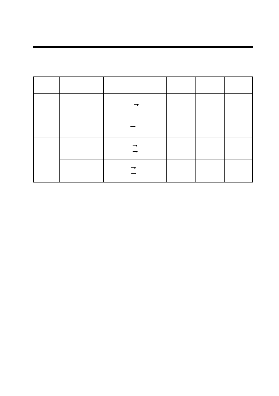
(Common Mode)
D
M
R
/
L
r
e
f
s
n
a
r
T
a
t
a
D
n
o
i
t
c
e
r
i
D
O
I
E
1
O
I
E
2
I
D
7
L
)
e
l
g
n
i
S
(
)
t
f
e
l
o
t
t
f
i
h
s
(
L
Y
0
6
1
Y
1
t
u
p
t
u
O
t
u
p
n
I
X
)
t
h
g
i
r
o
t
t
f
i
h
s
(
H
Y
1
Y
0
6
1
t
u
p
n
I
t
u
p
t
u
O
X
H
)
l
a
u
D
(
)
t
f
e
l
o
t
t
f
i
h
s
(
L
Y
0
6
1
Y
1
8
Y
0
8
Y
1
t
u
p
t
u
O
t
u
p
n
I
t
u
p
n
I
)
t
h
g
i
r
o
t
t
f
i
h
s
(
H
Y
1
Y
0
8
Y
1
8
Y
0
6
1
t
u
p
n
I
t
u
p
t
u
O
t
u
p
n
I
L
: V
SS
(0 V), H: V
DD
(+2.5V to +5.5V), X: Dont Care
Note: Dont care means that should be connected to H or L. Do not leave them open.
Tab.10

CONFIDENTIAL
EUREKA
EK7011TCB-1801
14 Rev 1.2 Oct.22.2001
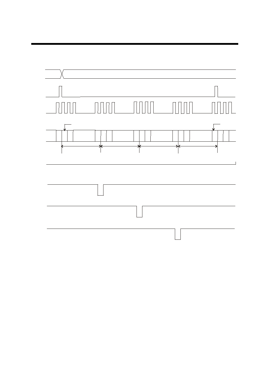
Connection Examples of Plural Segment Drives
(a) Case of L/R=L
(b) Case of L/R=H
8
Fig.7
Fig.8
CONFIDENTIAL
EUREKA
EK7011TCB-1801
15 Rev 1.2 Oct.22.2001
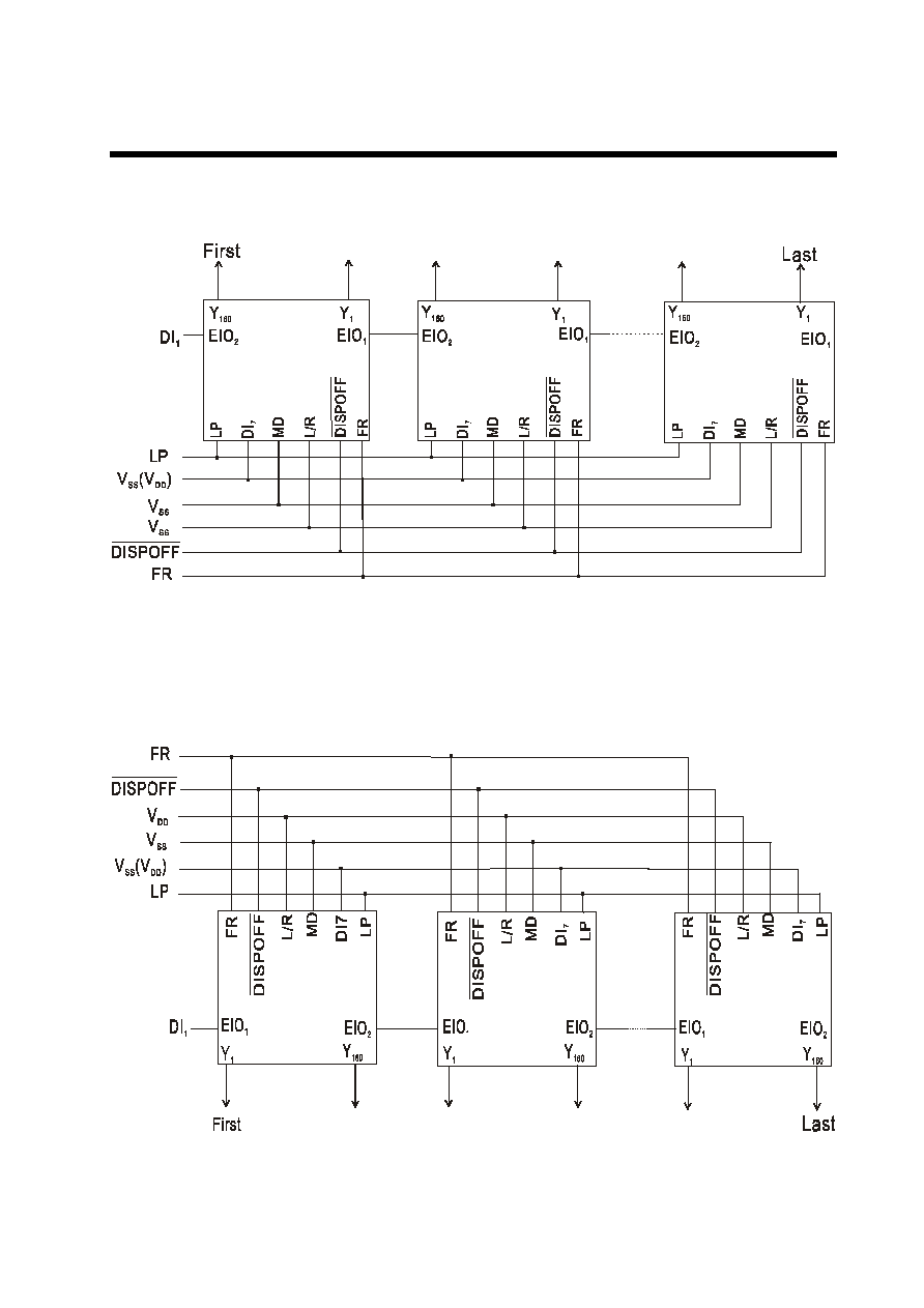
Timing Chart of 4-Device cascade Connection of Segment Drivers
E O
(d e v ic e C )
E O
(d e v ic e B )
E O
(D e v ic e A )
E I
H
n 1 2
n 1 2
n 1 2
n 1 2
n 1 2
(D e v ic e A )
(d e v ic e B )
(d e v ic e C )
(d e v ic e D )
To p D ATA
D I ~ D I
0
7
X C K
L P
F R
(* ) n : 4 -b it p a ra lle l m o d e 4 0
8 -b it p a ra lle l m o d e 2 0
L a s t D ATA
(D e v ic e A )
L
Fig.9
CONFIDENTIAL
EUREKA
EK7011TCB-1801
16 Rev 1.2 Oct.22.2001
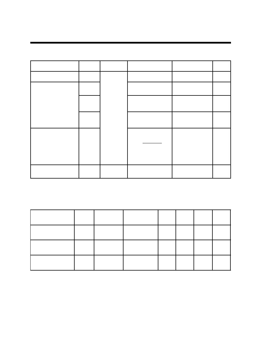
Connection Examples for Plural Common Drivers
Fig.10 Single Mode (Shifting toward left)
Fig.11 Single Mode (Shifting toward right)

CONFIDENTIAL
EUREKA
EK7011TCB-1801
17 Rev 1.2 Oct.22.2001
Fig.12 Dual Mode (Shifting toward left)
Fig.13 Dual Mode (Shifting toward right)
CONFIDENTIAL
EUREKA
EK7011TCB-1801
18 Rev 1.2 Oct.22.2001
Absolute Maximum Ratings
r
e
t
e
m
a
r
a
P
l
o
b
m
y
S
s
n
o
it
i
d
n
o
C
s
n
i
P
el
b
a
ci
l
p
p
A
s
g
n
it
a
R
ti
n
U
)
1
(
e
g
at
l
o
v
y
l
p
p
u
S
V
D
D
5
2
=
a
T
o
C
d
e
c
n
e
r
e
f
e
R
V
o
t
S
S
)
V
0
(
V
D
D
0
.
7
+
o
t
3
.
0
-
V
)
2
(
e
g
at
l
o
v
y
l
p
p
u
S
V
0
V
L
0
V
,
R
0
0
.
5
4
+
o
t
3
.
0
-
V
V
2
1
V
L
2
1
V
,
R
2
1
V
o
t
3
.
0
-
0
3
.
0
+
V
V
3
4
V
L
3
4
V
,
R
3
4
V
o
t
3
.
0
-
0
3
.
0
+
V
e
g
at
l
o
v
tu
p
n
I
V
I
I
D
7
-
0
,
R
/
L
,P
L
,
K
C
X
,
O
I
E
,
C
/
S
,
D
M
,
R
F
1
,
O
I
E
2
F
F
O
P
S
I
D
,
V
o
t
3
.
0
-
D
D
3
.
0
+
V
e
r
u
ta
r
e
p
m
et
e
g
a
r
o
t
S
g
ts
T
5
2
1
+
o
t
5
4
-
o
C
Recommended Operating Conditions
r
e
t
e
m
a
r
a
P
l
o
b
m
y
S
s
n
o
it
i
d
n
o
C
s
n
i
p
e
l
b
a
c
il
p
p
A
.
n
i
M
.
p
y
T
.
x
a
M
ti
n
U
)
1
(
e
g
a
tl
o
v
y
l
p
p
u
S
V
D
D
d
e
c
n
e
r
e
f
e
R
V
o
t
S
S
)
V
0
(
V
D
D
5
.
2
+
5
.
5
+
V
)
2
(
e
g
a
tl
o
v
y
l
p
p
u
S
V
0
V
L
0
V
,
R
0
0
.
5
1
+
0
4
+
V
g
n
it
a
r
e
p
O
e
r
u
t
a
r
e
p
m
e
t
T
a
0
2
-
5
8
+
o
C
Note
:
Ensure that voltages are set such that V
SS
<
V
43
<
V
12
<
V
0
Tab.11
Tab.12
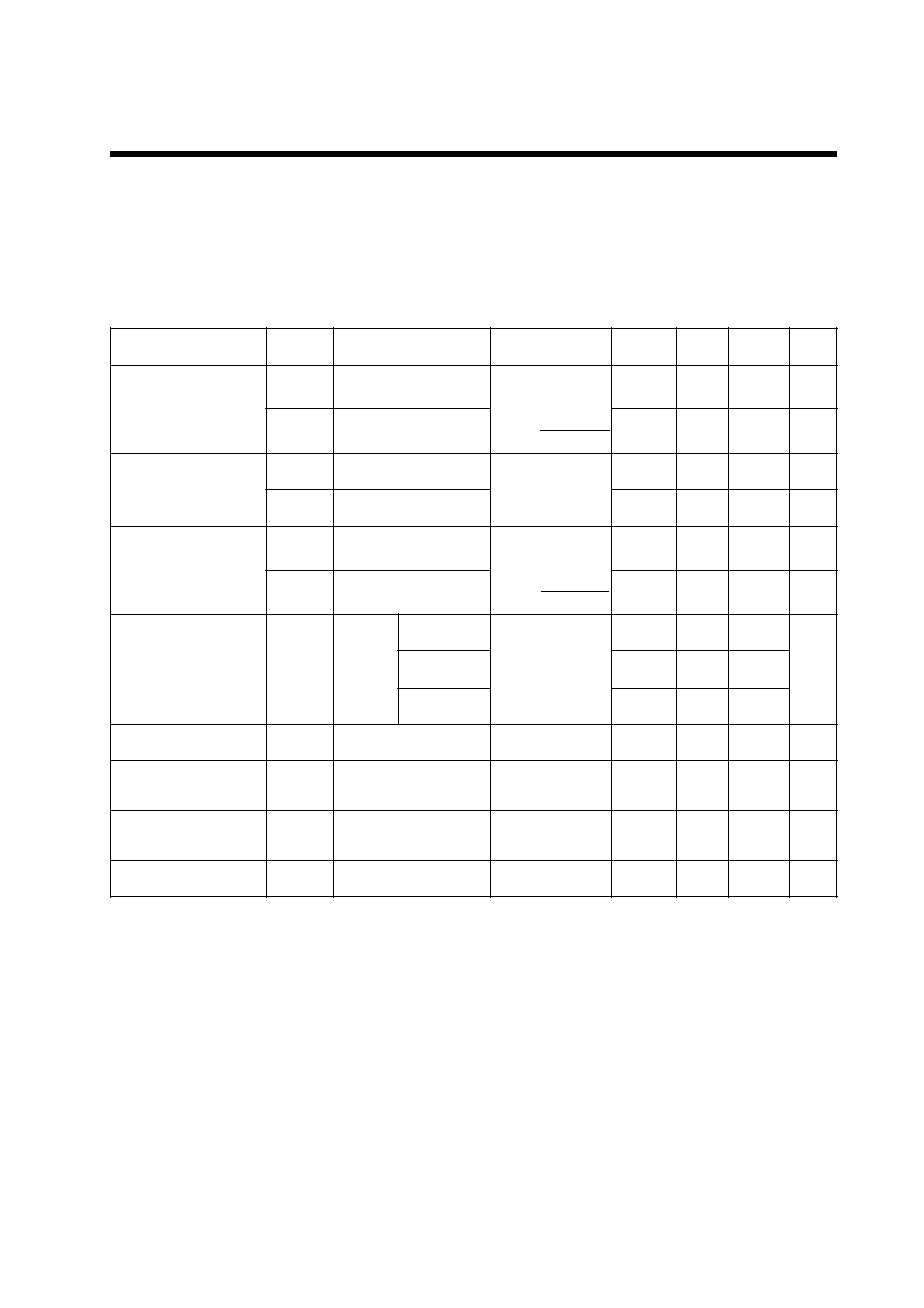
CONFIDENTIAL
EUREKA
EK7011TCB-1801
19 Rev 1.2 Oct.22.2001
Electrical Characteristics
DC Characteristics
(Segment Mode)
(V
SS
=0 V, V
DD
=+2.5V to +5.5V, V
0
=+15.0 to +40 V, Ta=-20 to +85
0
C )
r
e
t
e
m
a
r
a
P
l
o
b
m
y
S
s
n
o
i
ti
d
n
o
C
s
n
i
p
e
l
b
a
c
il
p
p
A
.
n
i
M
.
p
y
T
.
x
a
M
ti
n
U
e
g
a
tl
o
v
t
u
p
n
I
V
H
I
I
D
7
~
0
,
P
L
,
K
C
X
,
,
D
M
,
R
F
,
R
/
L
O
I
E
,
C
/
S
1
,
O
I
E
2
F
F
O
P
S
I
D
,
V
8
.
0
D
D
V
V
L
I
V
2
.
0
D
D
V
e
g
a
tl
o
v
t
u
p
t
u
O
V
H
O
I
H
O
A
m
4
.
0
-
=
O
I
E
1
O
I
E
,
2
V
D
D
4
.
0
-
V
V
L
O
I
L
O
A
m
4
.
0
+
=
4
.
0
+
V
e
g
a
k
a
e
l
t
u
p
n
I
t
n
e
r
r
u
c
I
H
I
L
V
I
V
=
D
D
I
D
7
~
0
,
P
L
,
K
C
X
,
,
D
M
,
R
F
,
R
/
L
O
I
E
,
C
/
S
1
,
O
I
E
2
F
F
O
P
S
I
D
,
0
.
0
1
+
I
L
I
L
V
I
V
=
S
S
0
.
0
1
-
e
c
n
a
t
s
i
s
e
r
t
u
p
t
u
O
R
N
O
V
|
N
O
|
V
5
.
0
=
V
0
V
0
.
0
4
+
=
Y
1
Y
-
0
6
1
7
.
0
0
.
1
V
0
V
0
.
0
3
+
=
0
.
1
5
.
1
V
0
V
0
.
0
2
+
=
5
.
1
0
.
2
t
n
e
r
r
u
c
y
b
-
d
n
a
t
S
I
T
S
B
1
*
V
s
s
0
.
0
5
)
1
(t
n
e
r
r
u
c
d
e
m
u
s
n
o
C
)
n
o
it
c
e
l
e
s
e
D
(
I
1
D
D
2
*
V
D
D
0
.
2
A
m
)
2
(t
n
e
r
r
u
c
d
e
m
u
s
n
o
C
)
n
o
it
c
e
l
e
S
(
I
2
D
D
3
*
V
D
D
0
.
8
A
m
t
n
e
r
r
u
c
d
e
m
u
o
s
n
o
C
I
0
4
*
V
0
0
.
1
A
m
�
K
Note:
*1 V
DD
=+5.0V, V
0
=+40V, V
I
=V
SS
*2 V
DD
=+5.0V, V
0
=+40V, f
XCK
=14MHz, No-load, EI=V
DD
The input data is turned over by data taking clock (4-bit parallel input mode)
*3 V
DD
=+5.0V, V
0
=+40V, f
XCK
=14MHz, No-load, EI=V
SS
The input data is turned over by data taking clock (4-bit parallel input mode)
*4 V
DD
=+5.0V, V
0
=+40V, f
XCK
=14MHz, f
LP
=41.6KHz, f
FR
=80Hz, No-load
The input data is turned over by data taking clock (4-bit parallel input mode)
Tab.13
�
A
�
A
�
A

CONFIDENTIAL
EUREKA
EK7011TCB-1801
20 Rev 1.2 Oct.22.2001
(Common Mode)
(V
SS
=0 V, V
DD
=+2.5V to +5.5V, V
0
=+15.0 to +40 V, Ta=-20 to +85
0
C )
r
e
t
e
m
a
r
a
P
l
o
b
m
y
S
s
n
o
i
t
i
d
n
o
C
s
n
i
p
e
l
b
a
c
i
l
p
p
A
.
n
i
M
.
p
y
T
.
x
a
M
t
i
n
U
e
g
a
t
l
o
v
t
u
p
n
I
V
H
I
I
D
7
~
0
,
,
K
C
X
,
P
L
,
R
/
L
,
R
F
,
D
M
,
C
/
S
O
I
E
1
,
O
I
E
2
,
F
F
O
P
S
I
D
V
8
.
0
D
D
V
V
L
I
V
2
.
0
D
D
V
e
g
a
t
l
o
v
t
u
p
t
u
O
V
H
O
I
H
O
A
m
4
.
0
-
=
O
I
E
1
,
O
I
E
2
V
D
D
4
.
0
-
V
V
L
O
I
L
O
A
m
4
.
0
+
=
4
.
0
+
V
e
g
a
k
a
e
l
t
u
p
n
I
t
n
e
r
r
u
c
I
H
I
L
V
1
V
=
D
D
I
D
6
~
0
,
R
/
L
,
P
L
,
,
C
/
S
,
D
M
,
R
F
F
F
O
P
S
I
D
0
.
0
1
+
I
L
I
L
V
1
V
=
S
S
I
D
7
~
0
,
,
K
C
X
,
P
L
,
R
/
L
,
R
F
,
D
M
,
C
/
S
O
I
E
1
,
O
I
E
2
,
F
F
O
P
S
I
D
0
.
0
1
-
n
w
o
d
-
l
l
u
p
t
u
p
n
I
t
n
e
r
r
u
c
I
D
P
V
1
V
=
D
D
O
I
E
,
K
C
X
1
O
I
E
,
2
,
I
D
7
0
.
0
0
1
e
c
n
a
t
s
i
s
e
r
t
u
p
t
u
O
R
N
O
V
|
N
O
|
V
5
.
0
=
V
0
V
0
.
0
4
+
=
Y
1
Y
~
0
6
1
7
.
0
0
.
1
V
0
V
0
.
0
3
+
=
0
.
1
5
.
1
V
0
V
0
.
0
2
+
=
5
.
1
0
.
2
t
n
e
r
r
u
c
y
b
-
d
n
a
t
S
I
T
S
B
1
*
V
s
s
0
.
0
5
d
e
m
u
s
n
o
C
)
1
(
t
n
e
r
r
u
c
I
D
D
2
*
V
D
D
0
8
0
.
d
e
m
u
s
n
o
C
)
2
(
t
n
e
r
r
u
c
I
O
2
*
V
0
0
6
1
0
.
K
�
*1 V
DD
=+5.0V, V0=+40V, V
I
=V
SS
*2 V
DD
=+5.0V, V0=+40V, f
LP
=41.6KHz, f
FR
=80Hz, case of 1/480 duty operation, No-load
Tab.14
�
A
�
A
�
A
�
A
�
A
�
A

CONFIDENTIAL
EUREKA
EK7011TCB-1801
21 Rev 1.2 Oct.22.2001
AC Characteristics
(Segment Mode 1)
(V
SS
=0 V, V
DD
=+4.5V to +5.5V, V
0
=+15.0 to +40 V, Ta=-20 to +85
0
C )
Note:
*1 Take the cascade connection into consideration
*2 (t
CK
-t
WCKH
-t
WCKL
) /2 is maximum in the case of high speed operation
r
e
t
e
m
a
r
a
P
l
o
b
m
y
S
n
o
it
i
d
n
o
C
.
n
i
M
.
p
y
T
.
x
a
M
ti
n
U
1
*
d
o
ir
e
p
k
c
o
l
c
tf
i
h
S
t
K
C
W
t
r
t,
f
s
n
0
1
1
7
s
n
h
t
d
i
w
e
s
l
u
p
"
H
"
k
c
o
l
c
tf
i
h
S
t
H
K
C
W
3
2
s
n
h
t
d
i
w
e
s
l
u
p
"
L
"
k
c
o
l
c
tf
i
h
S
t
L
K
C
W
3
2
s
n
e
m
it
p
u
t
e
s
a
t
a
D
t
S
D
0
1
s
n
e
m
it
d
l
o
H
a
t
a
D
t
H
D
0
2
s
n
h
t
d
i
w
e
s
l
u
p
"
H
"
e
s
l
u
p
h
c
t
a
L
t
H
P
L
W
3
2
s
n
o
t
e
s
ir
k
c
o
l
c
tf
i
h
S
e
m
it
e
s
ir
e
s
l
u
p
h
c
t
a
L
t
D
L
0
s
n
o
t
ll
a
f
k
c
o
l
c
tf
i
h
S
e
m
it
ll
a
f
e
s
l
u
p
h
c
t
a
L
t
L
S
5
2
s
n
o
t
e
s
ir
e
s
l
u
p
h
c
t
a
L
e
m
it
e
s
ir
k
c
o
l
c
tf
i
h
S
t
S
L
5
2
s
n
o
t
ll
a
f
e
s
l
u
p
h
c
t
a
L
e
m
it
ll
a
f
k
c
o
l
c
tf
i
h
S
t
H
L
5
2
s
n
2
*
e
m
it
e
s
ir
l
a
n
g
i
s
t
u
p
n
I
t
r
0
5
s
n
2
*
e
m
it
ll
a
f
l
a
n
g
i
s
t
u
p
n
I
t
f
0
5
s
n
e
m
it
p
u
t
e
s
e
l
b
a
n
E
t
s
1
2
s
n
e
m
it
l
a
v
o
m
e
r
F
F
O
P
S
I
D
t
D
S
0
0
1
s
n
h
t
d
i
w
e
s
l
u
p
"
L
"
F
F
O
P
S
I
D
t
L
D
W
2
.
1
)
1
(
e
m
it
y
a
l
e
d
t
u
p
t
u
O
t
D
C
L
F
p
5
1
=
0
4
s
n
)
2
(
e
m
it
y
a
l
e
d
t
u
p
t
u
O
t
1
d
p
t,
2
d
p
C
L
F
p
5
1
=
2
.
1
)
3
(
e
m
it
y
a
l
e
d
t
u
p
t
u
O
t
3
d
p
C
L
F
p
5
1
=
2
.
1
Tab.15
�
s
�
s
�
s

CONFIDENTIAL
EUREKA
EK7011TCB-1801
22 Rev 1.2 Oct.22.2001
(Segment Mode 2)
(V
SS
=0 V, V
DD
=+2.5V to +4.5V, V
0
=+15.0 to +40 V, Ta=-20 to +85
0
C )
r
e
t
e
m
a
r
a
P
l
o
b
m
y
S
n
o
it
i
d
n
o
C
.
n
i
M
.
p
y
T
.
x
a
M
ti
n
U
1
*
d
o
ir
e
p
k
c
o
l
c
tf
i
h
S
t
K
C
W
t
r
t,
f
s
n
1
1
5
2
1
s
n
h
t
d
i
w
e
s
l
u
p
"
H
"
k
c
o
l
c
tf
i
h
S
t
H
K
C
W
1
5
s
n
h
t
d
i
w
e
s
l
u
p
"
L
"
k
c
o
l
c
tf
i
h
S
t
L
K
C
W
1
5
s
n
e
m
it
p
u
t
e
s
a
t
a
D
t
S
D
0
3
s
n
e
m
it
d
l
o
H
a
t
a
D
t
H
D
0
4
s
n
h
t
d
i
w
e
s
l
u
p
"
H
"
e
s
l
u
p
h
c
t
a
L
t
H
P
L
W
1
5
s
n
o
t
e
s
ir
k
c
o
l
c
tf
i
h
S
e
m
it
e
s
ir
e
s
l
u
p
h
c
t
a
L
t
D
L
0
s
n
o
t
ll
a
f
k
c
o
l
c
tf
i
h
S
e
m
it
ll
a
f
e
s
l
u
p
h
c
t
a
L
t
L
S
1
5
s
n
o
t
e
s
ir
e
s
l
u
p
h
c
t
a
L
e
m
it
e
s
ir
k
c
o
l
c
tf
i
h
S
t
S
L
1
5
s
n
o
t
ll
a
f
e
s
l
u
p
h
c
t
a
L
e
m
it
ll
a
f
k
c
o
l
c
tf
i
h
S
t
H
L
1
5
s
n
2
*
e
m
it
e
s
ir
l
a
n
g
i
s
t
u
p
n
I
t
r
0
5
s
n
2
*
e
m
it
ll
a
f
l
a
n
g
i
s
t
u
p
n
I
t
f
0
5
s
n
e
m
it
p
u
t
e
s
e
l
b
a
n
E
t
s
6
3
s
n
e
m
it
l
a
v
o
m
e
r
F
F
O
P
S
I
D
t
D
S
0
0
1
s
n
h
t
d
i
w
e
s
l
u
p
"
L
"
F
F
O
P
S
I
D
t
L
D
W
2
.
1
)
1
(
e
m
it
y
a
l
e
d
t
u
p
t
u
O
t
D
C
L
F
p
5
1
=
8
7
s
n
)
2
(
e
m
it
y
a
l
e
d
t
u
p
t
u
O
t
1
d
p
t,
2
d
p
C
L
F
p
5
1
=
2
.
1
)
3
(
e
m
it
y
a
l
e
d
t
u
p
t
u
O
t
3
d
p
C
L
F
p
5
1
=
2
.
1
Note:
*1 Take the cascade connection into consideration
*2 (t
CK
-t
WCKH
-t
WCKL
) /2 is maximum in the case of high speed operation
Tab.16
�
s
�
s
�
s

CONFIDENTIAL
EUREKA
EK7011TCB-1801
23 Rev 1.2 Oct.22.2001
(Timing Characteristics of Segment Mode)
t
W L P H
t
W C K L
t
L H
t
W C K H
t
L D
t
L S
t
S L
t
r
t
f
t
W C K
L A S T D A TA
TOP DATA
t
D S
t
D H
t
W D L
T
S D
L P
X C K
D I
D I
0 ~
7
D I S P O F F
( )
*
1
2
n
t
D
L P
X C K
E I
E O
t
S
( * ) n : 4 - b i t p a ra l l e l m o d e 4 0
8 - b i t p a r a l l e l m o d e 2 0
t
p d 1
t
p d 2
T
p d 3
F R
L P
D I S P O F F
Y
Y
1 ~
1 6 0
Fig.14

CONFIDENTIAL
EUREKA
EK7011TCB-1801
24 Rev 1.2 Oct.22.2001
(Common Mode)
(V
SS
=0 V, V
DD
=+2.5V to +5.5V, V
0
=+15.0 to +40 V, Ta=-20 to +85
0
C )
r
e
t
e
m
a
r
a
P
l
o
b
m
y
S
n
o
it
i
d
n
o
C
.
n
i
M
.
p
y
T
.
x
a
M
ti
n
U
d
o
ir
e
p
k
c
o
l
c
tf
i
h
S
t
P
L
W
t
r
t,
f
s
n
0
2
0
5
2
s
n
h
t
d
i
w
e
s
l
u
p
"
H
"
k
c
o
l
c
tf
i
h
S
t
H
P
L
W
V
D
D
%
0
1
V
0
.
5
+
=
5
1
s
n
V
D
D
V
5
.
4
+
~
V
5
.
2
+
=
0
3
s
n
e
m
it
p
u
t
e
s
a
t
a
D
t
U
S
0
3
s
n
e
m
it
d
l
o
H
a
t
a
D
t
H
0
5
s
n
e
m
it
e
s
ir
l
a
n
g
i
s
t
u
p
n
I
t
r
0
5
s
n
e
m
it
ll
a
f
l
a
n
g
i
s
t
u
p
n
I
t
f
0
5
s
n
e
m
it
l
a
v
o
m
e
r
F
F
O
P
S
I
D
t
D
S
0
0
1
s
n
h
t
d
i
w
e
s
l
u
p
"
L
"
F
F
O
P
S
I
D
t
L
D
W
2
.
1
)
1
(
e
m
it
y
a
l
e
d
t
u
p
t
u
O
t
L
D
C
L
F
p
5
1
=
0
0
2
s
n
)
2
(
e
m
it
y
a
l
e
d
t
u
p
t
u
O
t
1
d
p
t
,
2
d
p
C
L
F
p
5
1
=
2
.
1
)
3
(
e
m
it
y
a
l
e
d
t
u
p
t
u
O
t
3
d
p
C
L
F
p
5
1
=
2
.
1
�
Tab.17
�
s
�
s
�
s
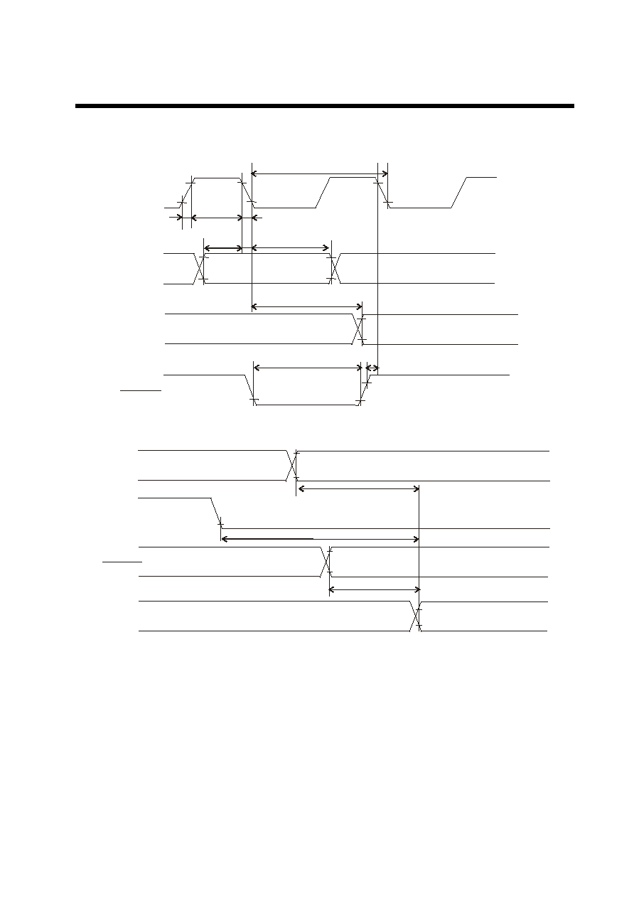
CONFIDENTIAL
EUREKA
EK7011TCB-1801
25 Rev 1.2 Oct.22.2001
(Timing Characteristics of Common Mode)
t
W L P H
t
H
L P
E I O
( D I )
2
7
t
r
t
f
t
W L P
t
S U
t
D L
t
S D
t
W D L
E I O
1
D I S P O F F
t
p d 1
t
p d 2
T
p d 3
F R
L P
D I S P O F F
Y
Y
1 ~
1 6 0
[ L / R = " L " ]
Fig.15
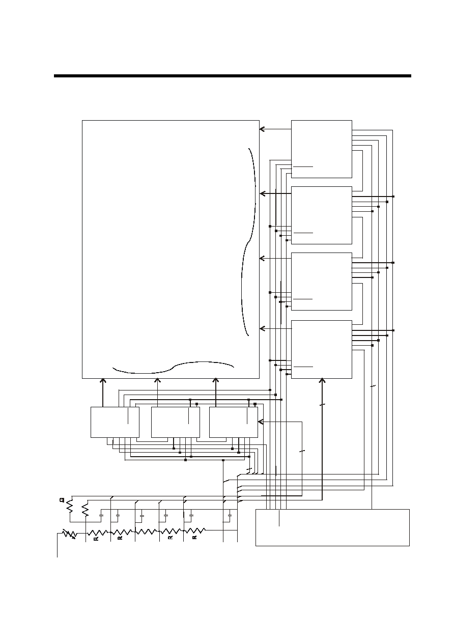
CONFIDENTIAL
EUREKA
EK7011TCB-1801
26 Rev 1.2 Oct.22.2001
(N
-4
)R
E
k7
0
(
4
)
LC
D
P
an
e
l
6
40 x
480
D
O
T
M
A
T
R
IX
C
om
1
C
om
2
C
om
48
0
C
om
47
9
S E G
64 0
S E G
63 9
S E G
2
S E G
1
EIO
1
M D
S/C
L/R
EIO
2
E
k7
0
11
(
4
)
EIO
1
M D
S/C
L/R
EIO
2
FR
LP
DISP OFF
XC K
E
k7
0
1
1
EIO
1
M D
S/C
L/R
FR
LP
DISP OFF
XC K
E
k7
0
EIO
1
M D
S/C
L/R
E
k7
0
EIO
1
M D
S/C
L/R
EIO
2
E
k7
0
11
M D
S/C
L/R
EIO
2
FR
LP
DISP OFF
XC K
E
k7
0
1
1
EIO
1
M D
S/C
L/R
EIO
2
FR
LP
DISP OFF
XC K
EIO
1
M D
S/C
L/R
EIO
2
(3
)
(2
)
(1
)
EIO
2
EIO
2
D
I
0
7
~
D
I
E
IO
1
M
D
S
/C
L/
R
E
IO
2
FR
LP
D
IS
P
O
FF
X
C
K
F
R
L
P
D
IS
P
O
F
F
X
C
K
E
IO
1
M
D
S
/C
L/
R
E
IO
2
E
IO
1
M
D
S
/C
L
/R
E
IO
2
F
R
L
P
D
IS
P
O
F
F
X
C
K
Y ~ Y
1
160
Y
D
F
R
L
P
D
IS
P
O
F
F
X
C
K
D
I
0
7
~
D
I
D
I
0
7
~
D
I
DI
0
7
~DI
DI
0
7
~DI
DI
0
7
~DI
DI
0
7
~DI
C o n tro lle r
D
I
0
7
~D
I
5
0~
1
00
V
E
E
V
0
V
1
V
2
V
3
V
4
V
D
D
V
ss
8
6
6
8
E
k7
0
1
1
(1
)
E
k7
0
1
1
(2
)
E
k7
0
1
1
(3
)
(C
as
e
of
1
/n
b
i
a
s
)
Y ~ Y
1
160
Y ~ Y
1
160
Y
~Y
1
16
0
Y
~Y
1
16
0
Y
~
Y
1
16
0
Y
~
Y
1
160
Example of system Configuration
Fig.16

CONFIDENTIAL
EUREKA
EK7011TCB-1801
27 Rev 1.2 Oct.22.2001
Example of Typical Characteristic
r
e
t
e
m
a
r
a
P
n
o
it
i
d
n
o
C
.
n
i
M
.
p
y
T
.
x
a
M
ti
n
U
g
n
it
a
R
l
a
t
n
e
m
a
d
n
u
F
l
a
c
i
p
y
T
e
m
i
T
y
a
l
e
D
n
o
it
a
g
a
p
o
r
P
5
2
+
=
a
T
0
V
,
V
0
=
s
s
V
,
C
D
D
V
0
.
5
+
=
0
1
s
n
Tab.18

CONFIDENTIAL
EUREKA
EK7011TCB-1801
28 Rev 1.2 Oct.22.2001
Precaution
l
Precaution when connecting or disconnecting the power
This LSI has a high-voltage LCD driver, so it may be permanently damaged by a high current which may
flow if a voltage is supplied to the LCD driver power supply while the logic system power supply is
floating.
The detail is as follows.
l
When connecting the power supply, connect the LCD drive power after connecting the logic system
power. Furthermore, when disconnecting the power, disconnect the logic system power after
disconnecting the LCD drive power.
l
We recommend you connecting the serial resistor(50~100
) or fuse to the LCD drive power V
0
of the
system as a current limitter. And set up the suitable value of the resistor in consideration of LCD display
grade.
And when connecting the logic power supply, the logic condition of this LSI inside is insecurity. Therefore
connect the LCD drive power supply after resetting logic condition of this LSI inside on DISPOFF function.
After that. cancel the DISPOFF function after the LCD drive power supply has become stable. Furthermore,
when disconnecting the power, set the LCD drive output pins to level V
SS
on DISPOFF function. After that,
disconnect the logic system power after disconnecting the LCD drive power. When connecting the power
supply, show the following recommend sequence.
V
D D
V
D D
V
S S
V
S S
V
S S
V
0
V
D D
D I S P O F F
V
0
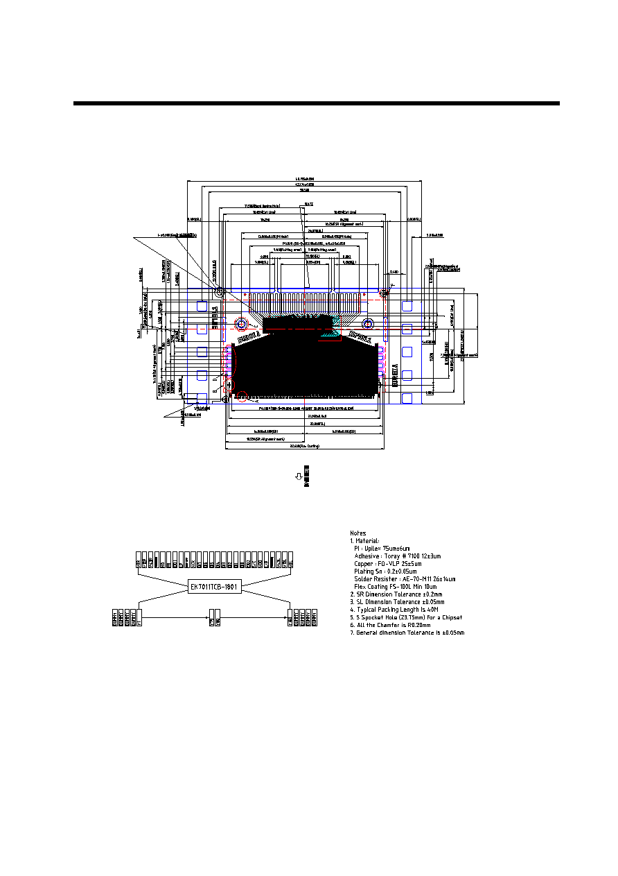
CONFIDENTIAL
EUREKA
EK7011TCB-1801
29 Rev 1.2 Oct.22.2001

CONFIDENTIAL
EUREKA
EK7011TCB-1801
30 Rev 1.2 Oct.22.2001


