
CONFIDENTIAL
DOC NO
TPL7603-0
REV
0.2
DOC Title
EK7603 Data Sheet
Page
/
/
Revision History
REV.
REV Date
Eff. Date
REV. Page
/
/
Revise item / Content
0.
0.2
2003/ /27
2003/6/5
2003/3/20
2003/6/ 7
P.5
New Issue
. OSEL = H or open H
OSEL = L L or open
2. When EDGSL = L L or open

CONFIDENTIAL
Eureka Microelectronics, Inc.
EK7603
402/480-Output TFT LCD Analog Source Driver
6F, NO.12, INNOVATION 1
ST
. RD.,
SCIENCE-BASED INDUSTRIAL PARK,
HSIN-CHU CITY, TAIWAN, R.O.C.
http://www.eureka.com.tw

CONFIDENTIAL
EUREKA
EK7603
June 2003 2 Preliminary Rev. 0.2
Table of Contents
Page
1.GENERAL DESCRIP TION
... ... ... ... ... ... ... ... ... ... ... ... ... ... ... ... ... ... ... ... ...
..... ...
.
3
2.FEATURES
... ... ... ... ... ... ... ... ... ... ... ... ... ... ... ... ... ... ... ... ... ... ... ... ... ... ... ... ... ...
.
3
3.BLOCK DIAGRAM
... ... ... ... ... ... ... ... ... ... ... ... ... ... ... ... ... ... ... ... ... ... ... ... ... ... ...
.
4
4.PIN FUNCTION DESCRIPTIONS
... ... ... ... ... ... ... ... ... ... ... ... ... ... ... ... ... ... ...
......
5
5.FUNCTION OPERATIONS
... ... ... ... ... ... ... ... ... ... ... ... ... ... ... ... ... ... ... ... ... ... ...
...
7
5.1 Operation timing
5.2 Number of output selection
5.3 Sampling modes
5.4 Color mode selection
5.5 Relationship between OE and output waveform
6.ABSOLUTE MAXIMUM RATINGS
... ... ... ... ... ... ... ... ... ... ... ... ... ... ... ..... ... ... ...
11
6.1 Absolute maximum ratings
6.2 Recommended operating conditions
7.ELECTRICAL CHARACTERISTICS
... ... ... ... ... ... ... ... ... ... ... ... ... ... ... ... ...
.... ...
12
7.1 DC characteristics
7.2 AC characteristics
7.3 Timing chart
8.DEFINITIONS
... ... ... ... ... ... ... ... ... ... ... ... ... ... ... ... ... ... ... ... ... ... ... ... ... ... ... ...
..
15
8.1 Data sheet status and application information
8.2 Life support application

CONFIDENTIAL
EUREKA
EK7603
June 2003 3 Preliminary Rev. 0.2
402/480- Output TFT LCD Analog Source Driver
1. GENERAL
DESCRIPTION
The EK7603 is an analog, fully color, source driver for TFT LCD panels designed for camera, TV etc.
Analog R, G and B signal are applied directly on the chip. For each of the 402/480 outputs, the voltage
is sampled and buffered to the panel. With a double sample and hold circuit a new voltage can be
sample whereas the previous sample voltage is applied to the panel.
According to different modes, the 3 input voltages (VA, VB, VC) can be applied on different output to
support various pixel array types.
The 3 input voltages (VA, VB, VC) can be sampled simultaneously or sequentially to have a better
flexibility with the input voltage. Using enable signal (STHx), several chips can be cascaded for large
panel.
2. FEATURES
402/480 analog source driver outputs (OSEL)
High frequency Sampling 10MHz
Automatic low power consumption mode after data capture (gated clock)
Bi-directional shift capability (L/R)
Simultaneous or Sequential RGB acquisition mode (MODE)
RGB color selection to match different types of color filters (Q1H, Q2H)
Output enable signal edge selectable (EDGSL)
Logic power supply voltage V
DD
: 2.7V � 5.25V
LCD power supply voltage AV
DD
: 4.5V � 5.5V
Output dynamic range AV
SS
+0.2V to AV
DD
-0.2V
Bare chip with gold bumper for COG application
CONFIDENTIAL
EUREKA
EK7603
June 2003 - 4 - Preliminary Rev. 0.2
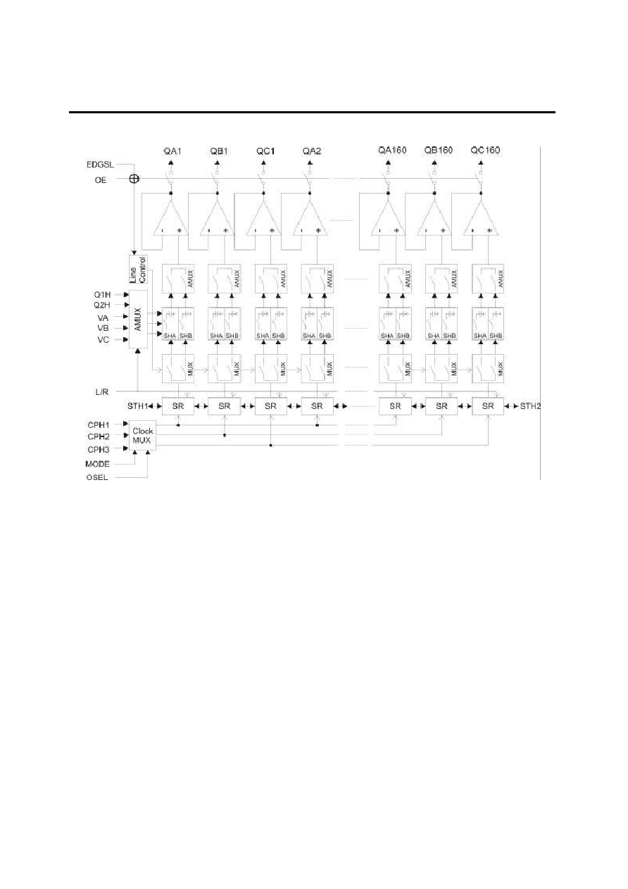
3. BLOCK
DIAGRAM
Fig. 1 Block diagram
Clock MUX
Selects if the sampling is simultaneous or sequential. Also gates the clock.
3 x 134/160-bit bi-directional shift register
Generates enable signals for sequential sampling 134/160 groups of 3 input colors.
Line control
Select sample circuit SHA or SHB and the high impedance output state
SH control MUX
Select which sample and hold circuit samples the analog input value.
AMUX
According to the controls signals, selects which input color goes to which group of outputs.
Sample and hold Circuit (SHA, SHB)
Sample the input voltage when the enable signal of the shift register is generated and hold this value
until it is stored on the panel.
Buffers
Drive the sample grayscale voltage on the panel.