Preliminary
Contents
1.
GENERAL DESCRIPTION..............................................................................................................................................4
2.
FEATURE ...........................................................................................................................................................................4
3.
APPLICATIONS ................................................................................................................................................................4
4.
PIN CONFIGURATIONS..................................................................................................................................................5
5.
FUNCTIONAL BLOCK DIAGRAM .............................................................................................................................13
6.
PIN DESCRIPTION.........................................................................................................................................................15
7.
FUNCTIONAL DESCRIPTION.....................................................................................................................................19
8.
CONTROL REGISTER...................................................................................................................................................48
9.
RELATIONSHIP BETWEEN SETTING AND COMMON/DISPLAY RAM............................................................74
10.
ABSOLUTE MAXIMUM RATINGS.........................................................................................................................75
11.
DC CHARACTERISTICS ..........................................................................................................................................76
12.
AC CHARACTERISTIC ............................................................................................................................................79
13.
APPLICATION CIRCUIT..........................................................................................................................................87
14.
COF INFORMATION.................................................................................................................................................91

Preliminary
EM65567
66 COM/ 96 SEG 256 Color STN LCD Driver
* This specification is subject to be changed without notice. 2003/1/9 (V0.1)
4
1. General description
EM65567 is one of the industry's most advanced wide-screen STN-LCD drivers for 256-color display. The industry's first
sub-screen display function makes it possible to display different images and data in a sub-screen inside the main LCD screen.
It also has a built-in display RAM, a power supply circuit for LCD drive, and an LCD controller circuit, therefore
contributing to compact system design. Its partial display function realizes low power consumption.
*Partial display function: A function that utilizes only part of the screen, thus reducing power consumption.
2. Feature
Display RAM capacity
Graphic: 96*64*(3+3+2)=49,152 bits
Icons: 96*2*(3+3+2)=1,536 bits
Ratio of display duty cycle: 1/10, 1/18, 1/26, 1/34, 1/42, 1/50, 1/58, 1/66
Outputs
Segment:96 RGB (288) outputs, Common: 66 outputs
Static driver: 2 outputs
Built-in display RAM and power supply circuit
Partial display functions
Switchable display in black and white mode
Bus connection with 80-family/ 68-family /Elan MCU
Serial interface is available
Logic power supply voltage: 1.8 to 3.3 V
LCD driving voltage: 5.0 to 12.0 V
Booster: 2 to 4 times
Write system cycle: 140 ns
Package (Ordering information):
Part Number
Package
Description
Package information
EM65567AGH
Gold bumped chip
NA
Page 5
EM65567AF
COF
64x96RGB (Version A)
Page 91
Note: The EM65567 series has the following sub-codes depending on their shapes.
H: Bare chip (Aluminum pad without bumped); GH: Gold bumped chip;
F: COF package; T: TAB (TCP) package
Example EM65567AF EM65567: Elan number ; A: Package Version ; F: COF package
3. Applications
Mobile phone
DSC
Small PDA

Preliminary
EM65567
66 COM/ 96 SEG 256 Color STN LCD Driver
* This specification is subject to be changed without notice. 2003/1/9 (V0.1)
5
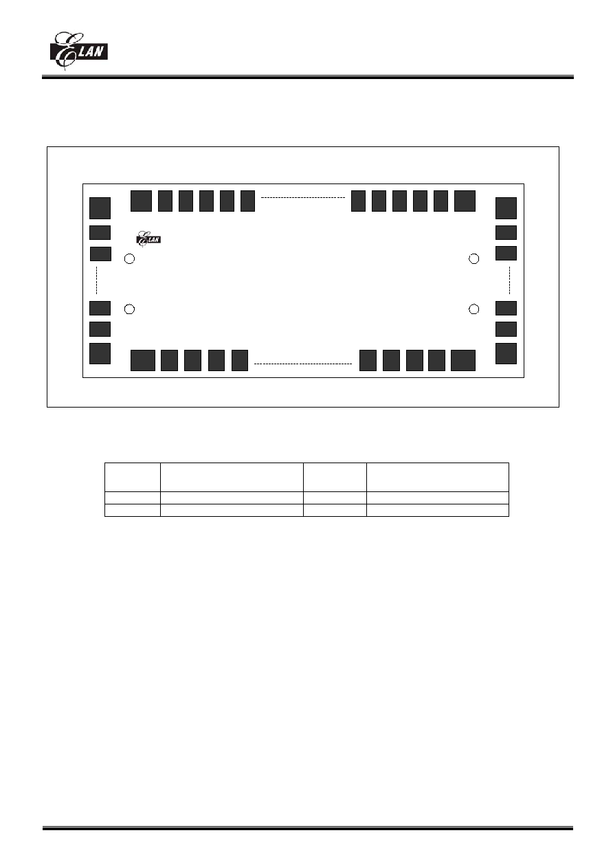
4. Pin
configurations
Figure 1. Pin configuration
Note: With the Elan logo in upper left the pin 1 is in the down left corner.
Mark
Coordinate (X,Y)
Mark
Coordinate (X,Y)
U-Left -7241.1
,141.6 U-Right 7247.9,141.6
D-Left -7241.1
,-208.4 D-Right 7247.9,-208.4
EM65567
1
197
198
227
228
521
522
551
U-Left
D-Left
U-Right
D-Right


