
Surface Mount Bridge Rectifier
DB101S THRU DB107S
Glass passivated type
Features
Plastic package has Underwriters Laboratory
Flammability Classification 94V-O Utilizing Flame
Retardant Epoxy Molding Compound.
For surface mounted applications.
Exceeds environmental standards of MIL-S-19500 /
228
High surge current capability
Ideal for printed circuit board
Mechanical data
Case : Molded plastic, DFS
Terminals : Solder plated, solderable per MIL-STD-750,
Method 2026
Polarity : Marked on body
Mounting Position : Any
Weight : 1.0 gram
( V )
( V )
( V )
( V )
(
o
C )
DB101S
DB101S
50
35
50
DB102S
DB102S
100
70
100
DB103S
DB103S
200
140
200
DB104S
DB104S
400
280
400
DB105S
DB105S
600
420
600
DB106S
DB106S
800
560
800
DB107S
DB107S
1000
700
1000
-55 to +125
O p e r a t i n g
t e m p e r a t u r e
V
R R M
* 1
V
R M S
* 2
V
R
* 3
V
F
* 4
S Y M B O L S
M A R K I N G
C O D E
1.1
MAXIMUM RATINGS
(AT T
A
=25
o
C unless otherwise noted)
PARAMETER
CONDITIONS
Symbol
MIN.
TYP.
MAX.
UNIT
Forward rectified current
See Fig.1
I
O
1.0
A
Forward surge current
8.3ms single half sine-wave superimposed on
rate load (JEDEC methode)
I
FSM
50
A
V
R
= V
RRM
T
A
= 25
o
C
10
uA
V
R
= V
RRM
T
A
= 125
o
C
500
uA
Storage temperature
T
STG
-55
+150
o
C
Reverse current
I
R
*1 Repetitive peak reverse voltage
*2 RMS voltage
*3 Continuous reverse voltage
*4 Maximum forward voltage
Formosa MS
Dimensions in inches and (millimeters)
.255(6.5)
.310(7.9)
.135(3.4)
.410(10.4)
.013(.33)
.060(1.5)
.205(5.2)
.365(9.3)
.042(1.1)
.245(6.2)
.290(7.4)
.115(2.9)
.360(9.4)
.003(.08)
.040(1.0)
.195(5.0)
.355(9.0)
.038(1.0)
+
~
~
DFS
0.1
1.0
.01
10
50
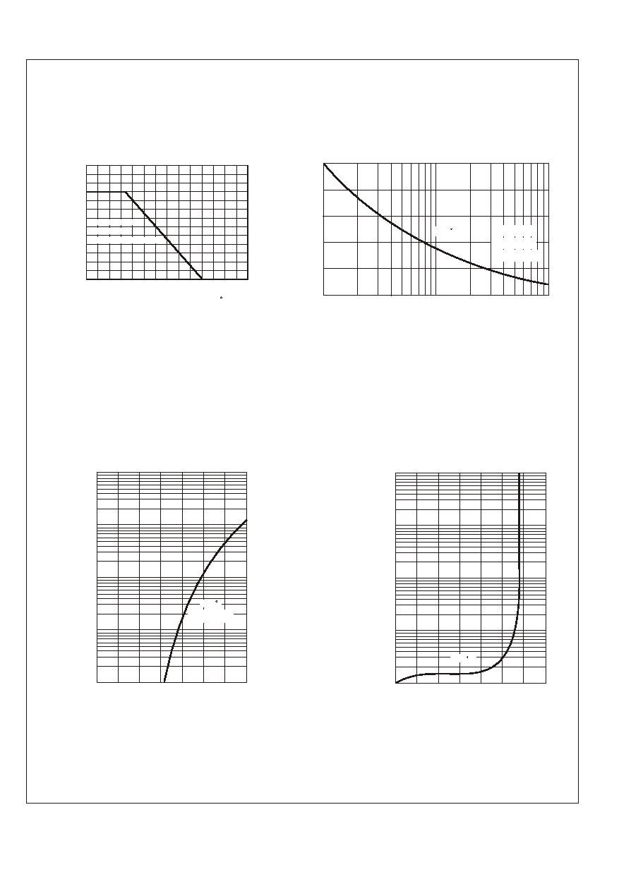
RATING AND CHARACTERISTIC CURVES (DB101S THRU DB107S)
FIG.4-TYPICAL REVERSE
CHARACTERISTICS
FIG.1-TYPICAL FORWARD CURRENT
A
V
E
R
A
G
E
F
O
R
W
A
R
D
C
U
R
R
E
N
T
,
(
A
)
PERCENTAGE OF PEAK REVERSE VOLTAGE, (%)
0.2
0.4
0.6
0.8
1.0
1.2
20 40 60 80 100 120 140
3.0
Single Phase
Half Wave 60Hz
Resistive Or Inductive Load
AMBIENT TEMPERATURE ( C)
DERATING CURVE
0.1
1.0
.01
10
50
FIG.3-TYPICAL FORWARD
CHARACTERISTICS
I
N
S
T
A
N
T
A
N
E
O
U
S
F
O
R
W
A
R
D
C
U
R
R
E
N
T
,
(
A
)
FORWARD VOLTAGE,(V)
Pulse Width 300us
1% Duty Cycle
0 .2 .4 .6 .8 1.0 1.2 1.4
3.0
R
E
V
E
R
S
E
L
E
A
K
A
G
E
C
U
R
R
E
N
T
,
(
m
A
)
0 25 50 75 100 125 150 175
Tj=25 C
Tj=25 C
FIG.2-MAXIMUM NON-REPETITIVE FORWARD
SURGE CURRENT
P
E
A
K
F
O
R
W
A
A
R
D
S
U
R
G
E
C
U
R
R
E
N
T
,
(
A
)
0
20
10
30
50
40
NUMBER OF CYCLES AT 60Hz
1
10
5
50
100
Tj=25 C
8.3ms Single Half
Sine Wave
JEDEC method