FM820 THRU FM860
Features
Plastic package has Underwriters Laboratory
Flammability Classification 94V-O Utilizing Flame
Retardant Epoxy Molding Compound.
For surface mounted applications.
Exceeds environmental standards of MIL-S-19500 /
228
Low leakage current.
Mechanical data
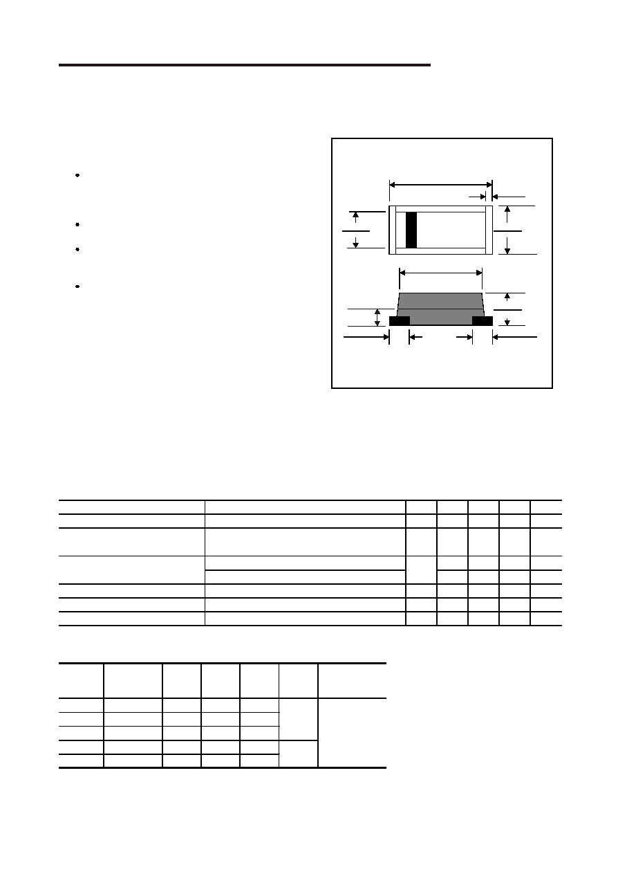
Case : Molded plastic, JEDEC DO-214AB
Terminals : Solder plated, solderable per MIL-STD-750,
Method 2026
Polarity : Indicated by c athode band
Mounting Position : Any
Weight : 0.00585 ounce, 0.195 gram
(V)
(V)
(V)
(V)
(
o
C)
FM820
SK82
20
14
20
FM830
SK83
30
21
30
FM840
SK84
40
28
40
FM850
SK85
50
35
50
FM860
SK86
60
42
60
0.70
SYMBOLS
MARKING
CODE
-55 to +125
Operating
temperature
V
RRM
*1
V
RMS
*2
V
R
*3
V
F
*4
0.65
MAXIMUM RATINGS
(AT T
A
=25
o
C unless otherwise noted)
PARAMETER
CONDITIONS
Symbol
MIN.
TYP.
MAX.
UNIT
Forward rectified current
See Fig.1
I
O
8.0
A
Forward surge current
8.3ms single half sine-wave superimposed on
rate load (JEDEC methode)
I
FSM
150
A
V
R
= V
RRM
T
A
= 25
o
C
5.0
mA
V
R
= V
RRM
T
A
= 100
o
C
50
mA
Thermal resistance
Junction to ambient
Rq
JA
55
o
C / w
Diode junction capacitance
f=1MHz and applied 4vDC reverse voltage
C
J
700
pF
Storage temperature
T
STG
-55
+150
o
C
Reverse current
I
R
*1 Repetitive peak reverse voltage
*2 RMS voltage
*3 Continuous reverse voltage
*4 Maximum forward voltage
Chip Schottky Barrier Diodes
Silicon epitaxial planer type
Formosa MS
0.276(7.0)
0.260(6.6)
0.012(0.3) Typ.
0.189(4.8)
0.173(4.4)
0.244(6.2)
0.228(5.8)
0.087(2.2)
0.071(1.8)
0.040 (1.0) Typ.
0.040(1.0) Typ.
Dimensions in inches and (millimeters)
SMC
0.152(3.8)
0.144(3.6)
0.032(0.8) Typ.
0.1
1.0
.01
10
50
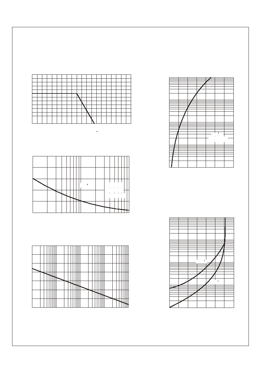
RATING AND CHARACTERISTIC CURVES (FM820 THRU FM860)
FIG.1-TYPICAL FORWARD CURRENT DERATING CURVE
A
V
E
R
A
G
E
F
O
R
W
A
R
D
C
U
R
R
E
N
T
,
(
A
)
FIG.3-MAXIMUM NON-REPETITIVE FORWARD
SURGE CURRENT
FIG.4-TYPICAL JUNCTION CAPACITANCE
REVERSE VOLTAGE,(V)
J
U
N
C
T
I
O
N
C
A
P
A
C
I
T
A
N
C
E
,
(
p
F
)
I
N
S
T
A
N
T
A
N
E
O
U
S
F
O
R
W
A
R
D
C
U
R
R
E
N
T
,
(
A
)
FORWARD VOLTAGE,(V)
Pulse Width 300us
1% Duty Cycle
2
4
6
8
10
12
2000
2400
2800
1600
1200
800
400
0
.01 .05 .1 .5 1 5 10 50 100
.1 .3 .5 .7 .9 1.1 1.3 1.5
.1
1.0
10
100
FIG.5 - TYPICAL REVERSE
CHARACTERISTICS
R
E
V
E
R
S
E
L
E
A
K
A
G
E
C
U
R
R
E
N
T
,
(
m
A
)
0 20 40 60 80 100 120 140
.01
Tj=75 C
Tj=25 C
Tj=25 C
100
50
0
150
250
200
NUMBER OF CYCLES AT 60Hz
1
10
5
50
100
Tj=25 C
8.3ms Single Half
Sine Wave
JEDEC method
PERCENT OF RATED PEAK REVERSE VOLTAGE,(%)
0
0
20
40
60
80
100
120
140
160
180
200
CASE TEMPERATURE,( C)
FIG.2-TYPICAL FORWARD
CHARACTERISTICS
P
E
A
K
F
O
R
W
A
R
D
S
U
R
G
E
C
U
R
R
E
N
T
,
(
A
)
P
E
A
K
F
O
R
W
A
R
D
S
U
R
G
E
C
U
R
R
E
N
T
,
(
A
)