
Freescale Semiconductor
Advance Information
This document contains information on a new product. Specifications and information herein
are subject to change without notice.
© Freescale Semiconductor, Inc., 2004. All rights reserved.
This document describes part-number-specific changes to
recommended operating conditions and revised electrical
specifications, as applicable, from those described in the general
MPC8245 Integrated Processor Hardware Specifications
(Order No. MPC8245EC). The MPC8245 combines a
PowerPCTM MPC603e core with a PCI bridge.
Specifications provided in this document supersede those in the
MPC8245 Integrated Processor Hardware Specifications, Rev. 3
or later, for the part numbers listed in
Table A
only.
Specifications not addressed in this document are unchanged.
Because this document is frequently updated, refer to
http://www.freescale.com or to your Freescale sales office for the
latest version.
Note that headings and table numbers in this document are not
consecutively numbered. They are intended to correspond to the
heading or table affected in the general hardware specification.
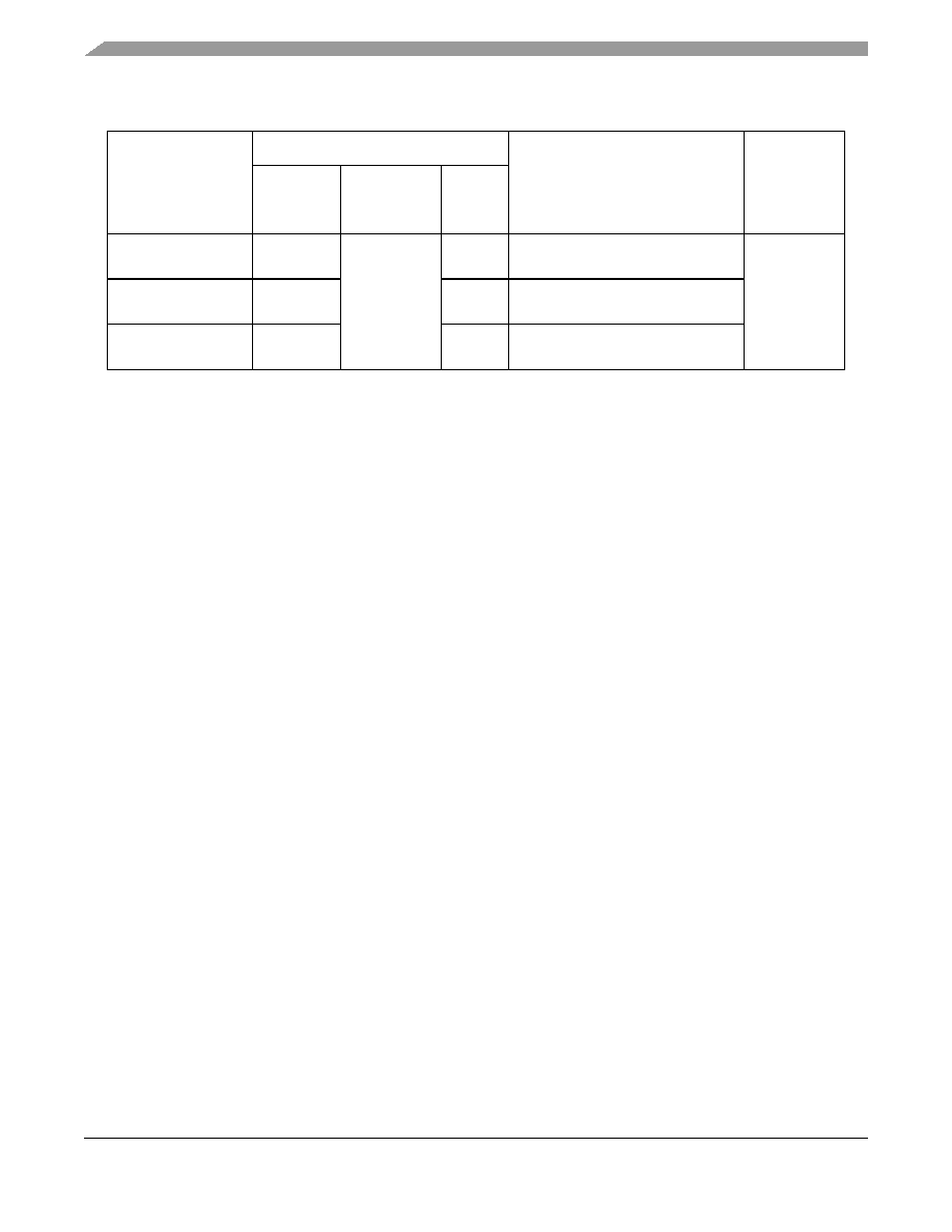
Part numbers addressed in this document are listed in Table A. For
more detailed ordering information, see
Section 9, "Ordering
Information
."
MPC8245ARZUPNS
Rev. 2, 07/2004
MPC8245
Part Number Specification for the
MPC8245ARZUnnnX Series
Freescale Part Numbers Affected:
MPC8245RZU400D
MPC8245ARZU400D
MPC8245ARZU466D
MPC8245 Part Number Specification for the MPC8245ARZUnnnX Series, Rev. 2
2
Freescale Semiconductor
Features
2
Features
This section summarizes changes to the power management feature of the MPC8245 described in the MPC8245
Integrated Processor Hardware Specifications.
3
General Parameters
This section summarizes changes to the general parameters of the MPC8245 core power supply described in the
MPC8245 Integrated Processor Hardware Specifications.
Table A. Part Numbers Addressed in this Data Sheet
Freescale
Part No.
Operating Conditions
Significant Differences from
Hardware Specification
Processor
Version
Register
Value
CPU
Frequency
(MHz)
V
DD
T
J
(∞C)
MPC8245RZU400D
400
2.1 ± 100 mV
0 to 85
Modified voltage and temperature
specifications to achieve 400 MHz
0x80811014
MPC8245ARZU400D
400
0 to 85
Modified voltage and temperature
specifications to achieve 400 MHz
MPC8245ARZU466D
466
0 to 85
Modified voltage and temperature
specifications to achieve 466 MHz
Note: The X prefix in a Freescale part number designates a `pilot production prototype' as defined by Freescale SOP
3-13. These are from a limited production volume of prototypes that are manufactured, tested, and inspected for quality
on a qualified technology to simulate normal production. These parts have only preliminary reliability and
characterization data. Before pilot production prototypes can be shipped, written authorization from the customer must
be on file in the applicable sales office acknowledging the qualification status and the fact that product changes may still
occur while shipping pilot production prototypes.
The `A' in the part number represents parts that are manufactured under a 29-angstrom process instead of the original
35-angstrom process.
MPC8245 Part Number Specification for the MPC8245ARZUnnnX Series, Rev. 2
Freescale Semiconductor
3
General Parameters
4.1.1
Absolute Maximum Ratings
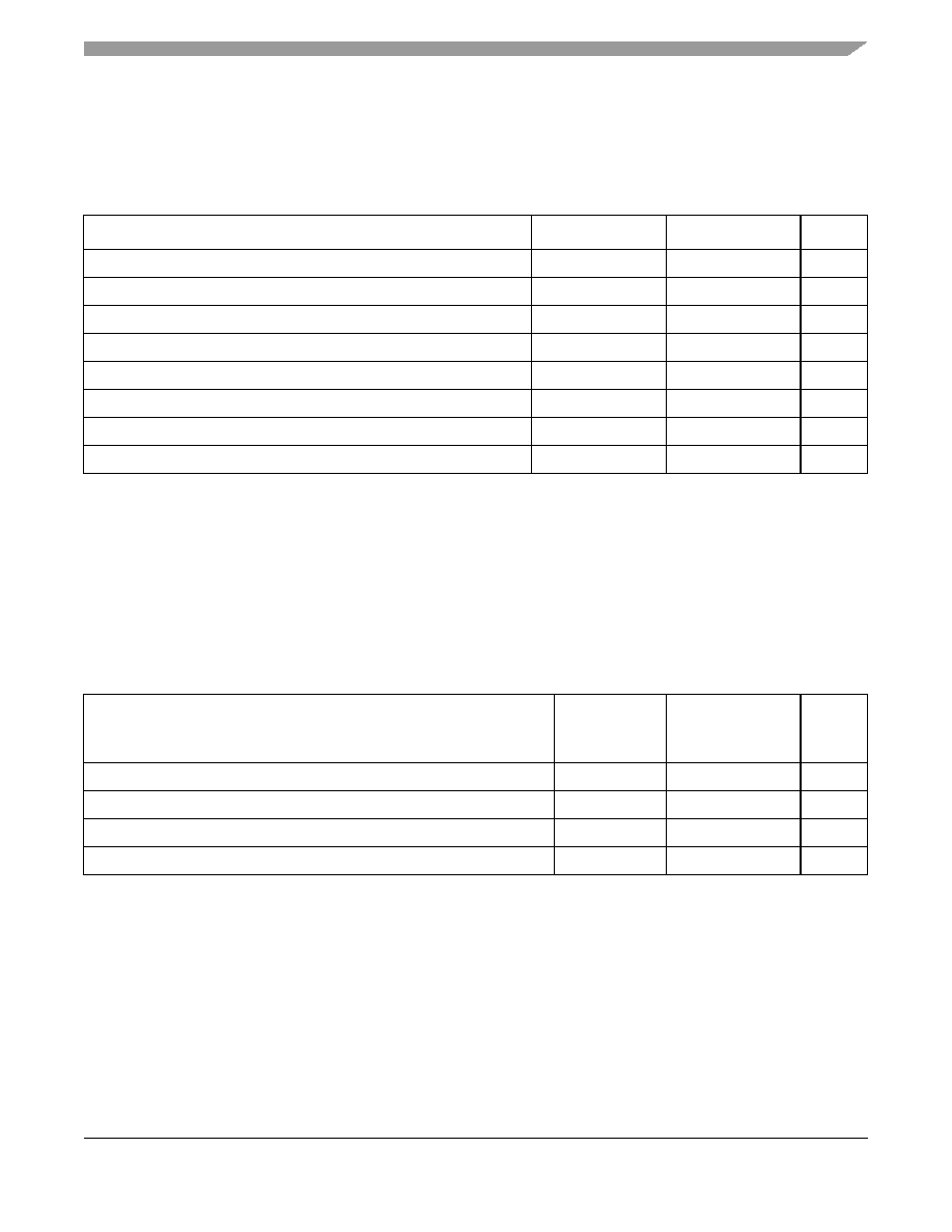
The tables in this section describe the MPC8245 DC electrical characteristics.
Table 1
provides the absolute
maximum ratings.
4.1.2
Recommended Operating Conditions
Table 2
provides the recommended operating conditions for the MPC8245 part numbers described herein.
Table 1. Absolute Maximum Ratings
Characteristic
1
Symbol
Range
Unit
Supply voltage--CPU core and peripheral logic
V
DD
≠0.3 to 2.2
V
Supply voltage--memory bus drivers
GV
DD
≠0.3 to 3.6
V
Supply voltage--PCI and standard I/O buffers
OV
DD
≠0.3 to 3.6
V
Supply voltage--PLLs
AV
DD
/AV
DD
2
≠0.3 to 2.2
V
Supply voltage--PCI reference
LV
DD
≠0.3 to 5.4
V
Input voltage
2
V
in
≠0.3 to 3.6
V
Operational die-junction temperature range
T
j
0 to 85
∞C
Storage temperature range
T
stg
≠55 to 150
∞C
Notes:
1.
Table 2
shows functional and tested operating conditions. Absolute maximum ratings are stress ratings only, and functional
operation at the maximums is not guaranteed. Stresses beyond those listed may affect device reliability or cause permanent
damage to the device.
2. PCI inputs with LV
DD
= 5 V ± 5% V DC may undergo corresponding stress at voltages exceeding LV
DD
+ 0.5 V DC.
Table 2. Recommended Operating Conditions
(1)
Notes:
1. Freescale tested these operating conditions and recommends them. Proper device operation outside of these conditions is
not guaranteed.
Characteristic
Symbol
Recommended
Value for
400 MHz CPU
Unit
Supply voltage
V
DD
2.1 V ± 100 mV
V
CPU PLL supply voltage
AV
DD
2.1 V ± 100 mV
V
PLL supply voltage--peripheral logic
AV
DD
2
2.1 V ± 100 mV
V
Die-junction temperature
(2)
2. For information about the thermal characteristics of this part, refer to the MPC8245 Integrated Processor Hardware
Specifications. Note that the lower die-junction temperature creates a greater need to use a heat sink with this part.
T
j
0 to 85
∞
C
MPC8245 Part Number Specification for the MPC8245ARZUnnnX Series, Rev. 2
4
Freescale Semiconductor
General Parameters
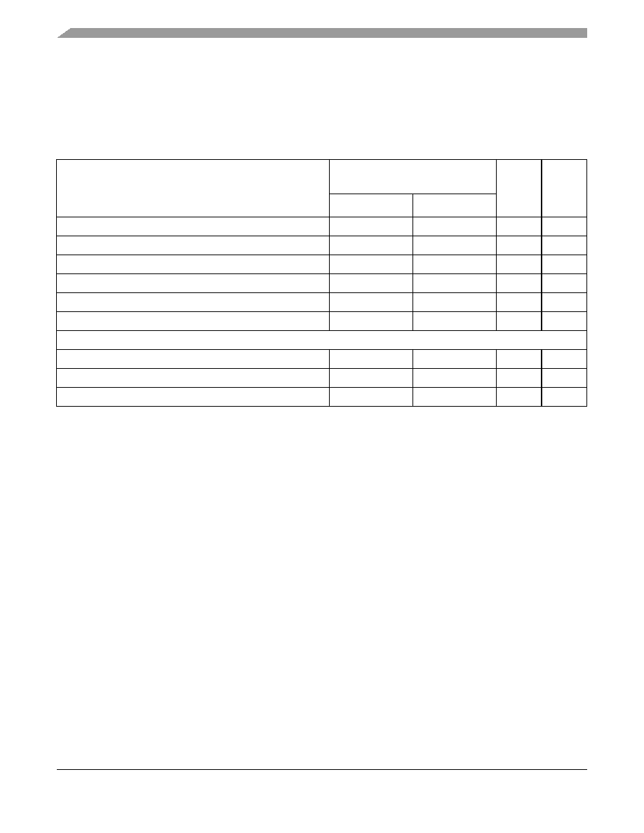
4.1.5
Power Characteristics
The AC electrical characteristics and AC timing for the parts described in this document are unaffected, and comply
with the MPC8245 Integrated Processor Hardware Specifications.
Table 5
provides the power consumption for the
MPC8245 part numbers described herein.
Table 5. Power Consumption
Mode
PCI Bus Clock/Memory Bus Clock
CPU Clock Frequency (MHz)
Unit
Notes
66/133/399
66/133/466
Typical
2.8
3.2
W
1, 5
Max--CFP
3.3
3.6
W
1, 2
Max--INT
2.8
3.1
W
1, 3
Doze
1.9
2.1
W
1, 4, 6
Nap
0.7
0.8
W
1, 4, 6
Sleep
0.4
0.4
W
1, 4, 6
I/O Power Supplies
10
Mode
Range
Range
Unit
Notes
Typ--OV
DD
140≠360
140≠360
mW
7, 8
Typ--GV
DD
340≠920
340≠930
mW
7, 9
Notes:
1.
The values include V
DD
, AV
DD
, and AV
DD
2, but do not include I/O supply power.
2.
Maximum--FP power is measured at V
DD
= 2.1 V with dynamic power management enabled while running an entirely
cache-resident, looping, floating point multiplication instruction.
3.
Maximum--INT power is measured at V
DD
= 2.1 V with dynamic power management enabled while running entirely
cache-resident, looping, integer instructions.
4.
Power saving mode maximums are measured at V
DD
= 2.1 V while the device is in doze, nap, or sleep mode.
5.
Typical power is measured at V
DD
= AV
DD
= 2.1 V, OV
DD
= 3.3 V where a nominal FP value, a nominal INT value, and a
value where there is a continuous flush of cache lines with alternating ones and zeros on 64-bit boundaries to local memory
are averaged.
6.
Power saving mode data measured with only two PCI_CLKs and two SDRAM_CLKs enabled.
7.
The typical minimum I/O power values was the result of the MPC8245 performing cache resident integer operations at the
slowest frequency combination of 33:66:200 (PCI:Mem:CPU) MHz.
8.
The typical maximum OV
DD
value resulted from the MPC8245 operating at the fastest frequency combination of
66:133:399 (PCI:Mem:CPU) MHz for the 400-MHz part, 66:133:466 (PCI:Mem:CPU) MHz for the 466-MHz part, and
performing continuous flushes of cache lines with alternating ones and zeros to PCI memory.
9.
The typical maximum GV
DD
value resulted from the MPC8245 operating at the fastest frequency combination of
66:133:399 (PCI:Mem:CPU) MHz for the 400-MHz part, 66:133:466 (PCI:Mem:CPU) MHz for the 466-MHz part, and
performing continuous flushes of cache lines with alternating ones and zeros on 64-bit boundaries to local memory.
10. Power consumption of PLL supply pins (AV
DD
and AV
DD
2) < 15 mW that the design guarantees but were not tested.
MPC8245 Part Number Specification for the MPC8245ARZUnnnX Series, Rev. 2
Freescale Semiconductor
5
General Parameters
4.3.1
Clock AC Specifications
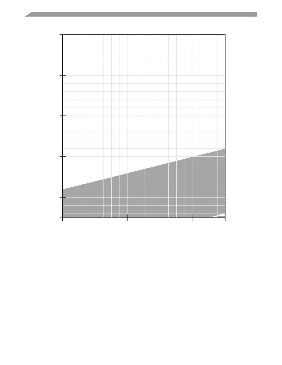
Figure 7
through
Figure 10
show the DLL locking range loop delay vs. frequency of operation for 29 angstrom parts
(400 and 466 MHz). These graphs define the areas of DLL locking for various modes. The gray areas show where
the DLL will lock.
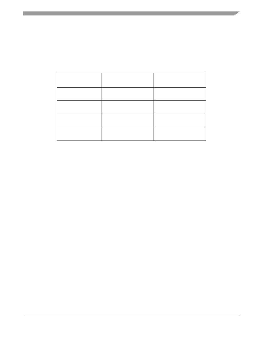
Register settings that define each DLL mode are shown in
Table 9
.
The DLL_MAX_DELAY bit can lengthen the amount of time through the delay line. This is accomplished by
increasing the time between each of the 128 tap points in the delay line. Although this increased time makes it easier
to guarantee that the reference clock will be within the DLL lock range, it also means there may be slightly more
jitter in the output clock of the DLL, should the phase comparator shift the clock between adjacent tap points. Refer
to Freescale application note AN2164, MPC8245/MPC8241 Memory Clock Design Guidelines, for details on
memory design.
Table 9. DLL Mode Definition
DLL Mode
Value of Bit 2 of Config
Register at 0x76
Value of Bit 7 of Config
Register at 0x72
Normal tap delay,
No DLL extend
0
0
Normal tap delay,
DLL extend
0
1
Max tap delay,
No DLL extend
1
0
Max tap delay,
DLL extend
1
1
MPC8245 Part Number Specification for the MPC8245ARZUnnnX Series, Rev. 2
6
Freescale Semiconductor
General Parameters
Figure 7. DLL Locking Range Loop Delay vs. Frequency of Operation for DLL_Extend = 0
and Normal Tap Delay
2
3
10
15
20
0
25
30
1
T
loop
Propagation Delay Time (ns)
T
cl
k
SDRAM_SYNC_OUT Per
i
od (
n
s
)
N = 1
N = 2
7.5
4
5
MPC8245 Part Number Specification for the MPC8245ARZUnnnX Series, Rev. 2
Freescale Semiconductor
7
General Parameters
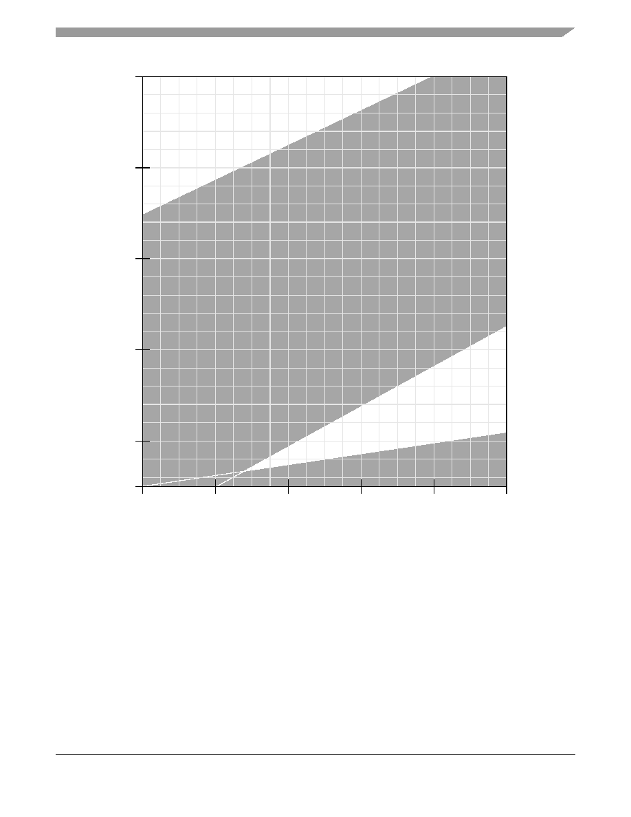
Figure 8. DLL Locking Range Loop Delay vs. Frequency of Operation for DLL_Extend = 1
and Normal Tap Delay
2
3
10
15
20
0
25
30
1
T
loop
Propagation Delay Time (ns)
T
cl
k
SDRAM_SYNC_OUT
Per
i
od
(
n
s
)
N = 1
N = 2
7.5
4
5
MPC8245 Part Number Specification for the MPC8245ARZUnnnX Series, Rev. 2
8
Freescale Semiconductor
General Parameters
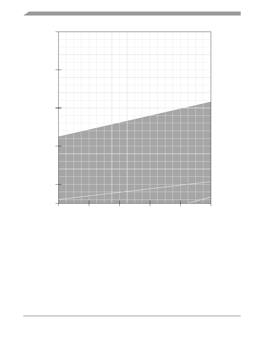
Figure 9. DLL Locking Range Loop Delay vs. Frequency of Operation for DLL_Extend = 0
and Max Tap Delay
2
3
10
15
20
0
25
30
1
T
loop
Propagation Delay Time (ns)
T
cl
k
SDRAM_SYNC_OUT Per
i
od (
n
s
)
N = 1
N = 2
7.5
4
5
MPC8245 Part Number Specification for the MPC8245ARZUnnnX Series, Rev. 2
Freescale Semiconductor
9
General Parameters
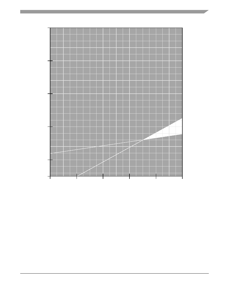
Figure 10. DLL Locking Range Loop Delay vs. Frequency of Operation for DLL_Extend = 1
and Max Tap Delay
2
3
10
15
20
0
25
30
1
T
loop
Propagation Delay Time (ns)
T
cl
k
SDRAM_SYNC_OUT
Per
i
od
(
n
s
)
N = 1
N = 2
7.5
4
5
MPC8245 Part Number Specification for the MPC8245ARZUnnnX Series, Rev. 2
10
Freescale Semiconductor
General Parameters
4.3.3
Output AC Timing Specification
Table 11
provides the processor bus AC timing specification for output hold time for debug signals in the 466-MHz
CPU of the MPC8245 at recommended operating conditions (see
Table 2
) with LV
DD
= 3.3 V ± 0.3 V. All output
timings assume a purely resistive 50-
load (see Figure 14 in the MPC8245 Integrated Processor Hardware
Specifications). Output timings are measured at the pin; time-of-flight delays must be added for trace lengths, vias,
and connectors in the system. These specifications are for the default driver strengths listed in the MPC8245
Integrated Processor Hardware Specifications.
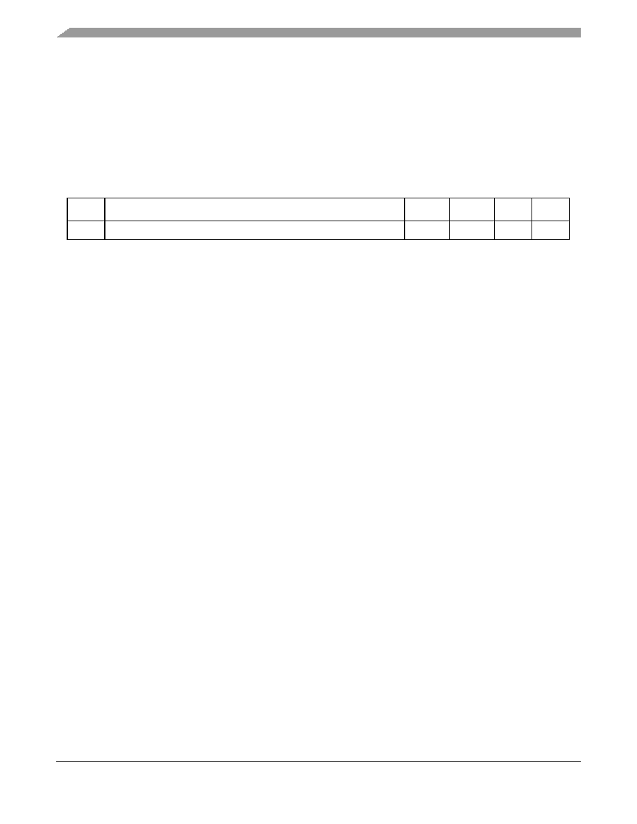
Table 11. Output AC Timing Specifications
Num
Characteristic
Min
Max
Unit
Notes
13b
Output hold (debug signals)
0.0
--
ns
1
Note:
1. All memory and related interface output signal specifications are specified from the VM = 1.4 V of the rising edge of the
memory bus clock, SDRAM_SYNC_IN to the TTL level (0.8 or 2.0 V) of the signal in question. SDRAM_SYNC_IN is
the same as PCI_SYNC_IN in 1:1 mode, but is twice the frequency in 2:1 mode (processor/memory bus clock rising
edges occur on every rising and falling edge of PCI_SYNC_IN).

MPC8245 Part Number Specification for the MPC8245ARZUnnnX Series, Rev. 2
Freescale Semiconductor
11
PLL Configuration
6
PLL Configuration
The MPC8245 internal PLLs are configured by the PLL_CFG[0:4] signals. For a given PCI_SYNC_IN (PCI bus)
frequency, the PLL configuration signals set both the peripheral logic/memory bus PLL (VCO) frequency of
operation for the PCI-to-memory frequency multiplying and the MPC603e CPU PLL (VCO) frequency of operation
for memory-to-CPU frequency multiplying. The PLL configurations for the 400- and 466-MHz parts are shown in
Table 18
and
Table 19
, respectively.
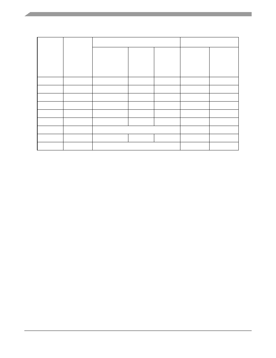
Table 18. PLL Configurations for the 400-MHz Part Offering
Ref
PLL_CFG
[0:4]
11,14,15
400-MHz Part
9
Multipliers
PCI Clock Input
(PCI_SYNC_IN)
Range
1
(MHz)
Periph
Logic/Mem
Bus Clock
Range
(MHz)
CPU Clock
Range
(MHz)
PCI-to-Mem
(Mem VCO)
Mem-to-CPU
(CPU VCO)
0
00000
25≠44
2
75≠132
188≠330
3 (2)
2.5 (2)
1
00001
25≠44
5
75≠132
225≠396
3 (2)
3 (2)
2
00010
13
50
9
≠66
1
50≠66
225≠297
1 (4)
4.5 (2)
3
00011
16
50
8
≠66
1
50≠66
100≠133
1 (Bypass)
2 (4)
4
00100
25≠46
4
50≠92
100≠184
2 (4)
2 (4)
6
00110
17
Bypass
Bypass
Bypass
7 (Rev. B)
00111
60
6
≠66
1
60≠66
180≠198
1 (Bypass)
3 (2)
7 (Rev. D)
00111
13
25≠28
5
100≠112
350≠392
4 (2)
3.5 (2)
8
01000
60
6
≠66
1
60≠66
180≠198
1 (4)
3 (2)
9
01001
45
6
≠66
1
90≠132
180≠264
2 (2)
2 (2)
A
01010
25≠44
5
50≠88
225≠396
2 (4)
4.5 (2)
B
01011
45
3
≠66
1
68≠99
204≠297
1.5 (2)
3 (2)
C
01100
36
6
≠46
4
72≠92
180≠230
2 (4)
2.5 (2)
D
01101
45
3
≠66
1
68≠99
238≠347
1.5 (2)
3.5 (2)
E
01110
30
6
≠46
4
60≠92
180≠276
2 (4)
3 (2)
F
01111
25≠38
5
75≠114
263≠399
3
(2)
3.5
(2)
10
10000
30≠44
2
60≠132
180≠264
3 (2)
2 (2)
11
10001
25≠33
2
100≠132
250≠330
4 (2)
2.5 (2)
12
10010
60
6
≠66
1
90≠99
180≠198
1.5 (2)
2 (2)
13
10011
25≠33
5
100≠132
300≠396
4 (2)
3 (2)
14
10100
26
6
≠47
4
52≠94
182≠329
2 (4)
3.5 (2)
15
10101
27
3
≠40
5
68≠100
272≠400
2.5 (2)
4 (2)
16
10110
25≠46
4
50≠92
200≠368
2 (4)
4 (2)
17
10111
25≠33
2
100≠132
200≠264
4 (2)
2 (2)
MPC8245 Part Number Specification for the MPC8245ARZUnnnX Series, Rev. 2
12
Freescale Semiconductor
PLL Configuration
18
11000
27
3
≠53
5
68≠132
204≠396
2.5 (2)
3 (2)
19
11001
36
6
≠66
1
72≠132
180≠330
2 (2)
2.5 (2)
1A
11010
50
9
≠66
1
50≠66
200≠264
1 (4)
4 (2)
1B
11011
13
34
3
≠66
1
68≠132
204≠396
2 (2)
3 (2)
1C
11100
44
6
≠66
1
66≠99
198≠297 1.5
(2)
3
(2)
1D
11101
48
6
≠66
1
72≠99
180≠248
1.5 (2)
2.5 (2)
1E (Rev. B)
11110
10
Not usable
Off
Off
1E (Rev. D)
11110
33
3
≠57
5
66≠114
231≠399
2 (2)
3.5 (2)
1F
11111
10
Not usable
Off
Off
Notes:
1.
Limited by maximum PCI input frequency (66 MHz).
2.
Limited by maximum system memory interface operating frequency (133 MHz).
3.
Limited by minimum memory VCO frequency (132 MHz).
4.
Limited due to maximum memory VCO frequency (372 MHz).
5.
Limited by maximum CPU operating frequency (400 MHz).
6.
Limited by minimum CPU VCO frequency (360 MHz).
7.
Limited by maximum CPU VCO frequency (800 MHz).
8.
Limited by minimum CPU operating frequency (100 MHz).
9.
Limited by minimum memory bus frequency (50 MHz).
10. In clock off mode, no clocking occurs inside the MPC8245, regardless of the PCI_SYNC_IN input.
11. Range values are shown rounded down to the nearest whole number (decimal place accuracy removed) for
clarity.
12. PLL_CFG[0:4] settings that are not listed are reserved.
13. Multiplier ratios for this PLL_CFG[0:4] setting are different from the MPC8240 and are not
backwards-compatible.
14. PCI_SYNC_IN range for this PLL_CFG[0:4] setting is different from the MPC8240 and may not be fully
backwards-compatible.
15. Bits 7≠4 of register offset <0xE2> contain the PLL_CFG[0:4] setting value.
16. In PLL bypass mode, the PCI_SYNC_IN input signal clocks the internal processor directly, the peripheral
logic PLL is disabled, and the bus mode is set for 1:1 (PCI:Mem) mode operation. This mode is intended for
hardware modeling support. The AC timing specifications given in this document do not apply in the PLL
bypass mode.
17. In dual PLL bypass mode, the PCI_SYNC_IN input signal clocks the internal peripheral logic directly, the
peripheral logic PLL is disabled, and the bus mode is set for 1:1 (PCI_SYNC_IN:Mem) mode operation. In
this mode, the OSC_IN input signal clocks the internal processor directly in 1:1 (OSC_IN:CPU) mode
operation, and the processor PLL is disabled. The PCI_SYNC_IN and OSC_IN input clocks must be
externally synchronized. This mode is intended for hardware modeling support. The AC timing specifications
given in this document do not apply in the dual PLL bypass mode.
Table 18. PLL Configurations for the 400-MHz Part Offering (continued)
Ref
PLL_CFG
[0:4]
11,14,15
400-MHz Part
9
Multipliers
PCI Clock Input
(PCI_SYNC_IN)
Range
1
(MHz)
Periph
Logic/Mem
Bus Clock
Range
(MHz)
CPU Clock
Range
(MHz)
PCI-to-Mem
(Mem VCO)
Mem-to-CPU
(CPU VCO)
MPC8245 Part Number Specification for the MPC8245ARZUnnnX Series, Rev. 2
Freescale Semiconductor
13
PLL Configuration
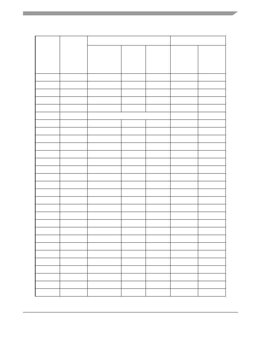
Table 19. PLL Configurations for the 466-MHz Part Offering
Ref
PLL_CFG
[0:4]
11,14,15
466-MHz Part
9
Multipliers
PCI Clock Input
(PCI_SYNC_IN)
Range
1
(MHz)
Periph
Logic/Mem
Bus Clock
Range
(MHz)
CPU Clock
Range
(MHz)
PCI-to-Mem
(Mem VCO)
Mem-to-CPU
(CPU VCO)
0
00000
25≠44
2
75≠132
188≠330
3 (2)
2.5 (2)
1
00001
25≠44
2
75≠132
225≠396
3 (2)
3 (2)
2
00010
13
50
9
≠66
1
50≠66
225≠297
1 (4)
4.5 (2)
3
00011
16
50
8
≠66
1
50≠66
100≠133
1 (Bypass)
2 (4)
4
00100
25≠46
4
50≠92
100≠184
2 (4)
2 (4)
6
00110
17
Bypass
Bypass
Bypass
7 00111
25≠33
2
100≠133
350≠466
4 (2)
3.5 (2)
8
01000
60
6
≠66
1
60≠66
180≠198
1 (4)
3 (2)
9
01001
45
6
≠66
1
90≠132
180≠264
2 (2)
2 (2)
A
01010
25≠46
4
50≠96
225≠432
2 (4)
4.5 (2)
B
01011
45
3
≠66
1
68≠99
204≠297
1.5 (2)
3 (2)
C
01100
36
6
≠46
4
72≠92
180≠230
2 (4)
2.5 (2)
D
01101
45
3
≠66
1
68≠99
238≠347
1.5 (2)
3.5 (2)
E
01110
30
6
≠46
4
60≠92
180≠276
2 (4)
3 (2)
F
01111
25≠44
2
75≠132 263≠462
3
(2)
3.5
(2)
10
10000
30
6
≠44
2
60≠132
180≠264
3 (2)
2 (2)
11
10001
25≠33
2
100≠132
250≠330
4 (2)
2.5 (2)
12
10010
60
6
≠66
1
90≠99
180≠198
1.5 (2)
2 (2)
13
10011
25≠33
2
100≠132
300≠396
4 (2)
3 (2)
14
10100
26
6
≠47
4
52≠94
182≠329
2 (4)
3.5 (2)
15
10101
27
3
≠46
5
68≠115
272≠460
2.5 (2)
4 (2)
16
10110
25≠46
4
50≠92
200≠368
2 (4)
4 (2)
17
10111
25≠33
2
100≠132
200≠264
4 (2)
2 (2)
18
11000
27
3
≠53
2
68≠132
204≠396
2.5 (2)
3 (2)
19
11001
36
6
≠66
1
72≠132
180≠330
2 (2)
2.5 (2)
1A
11010
50
9
≠66
1
50≠66
200≠264
1 (4)
4 (2)
1B
11011
13
34
3
≠66
1
68≠132
204≠396
2 (2)
3 (2)
1C
11100
44
6
≠66
1
66≠99
198≠297 1.5
(2)
3
(2)
1D
11101
48
6
≠66
1
72≠99
180≠248
1.5 (2)
2.5 (2)
MPC8245 Part Number Specification for the MPC8245ARZUnnnX Series, Rev. 2
14
Freescale Semiconductor
PLL Configuration
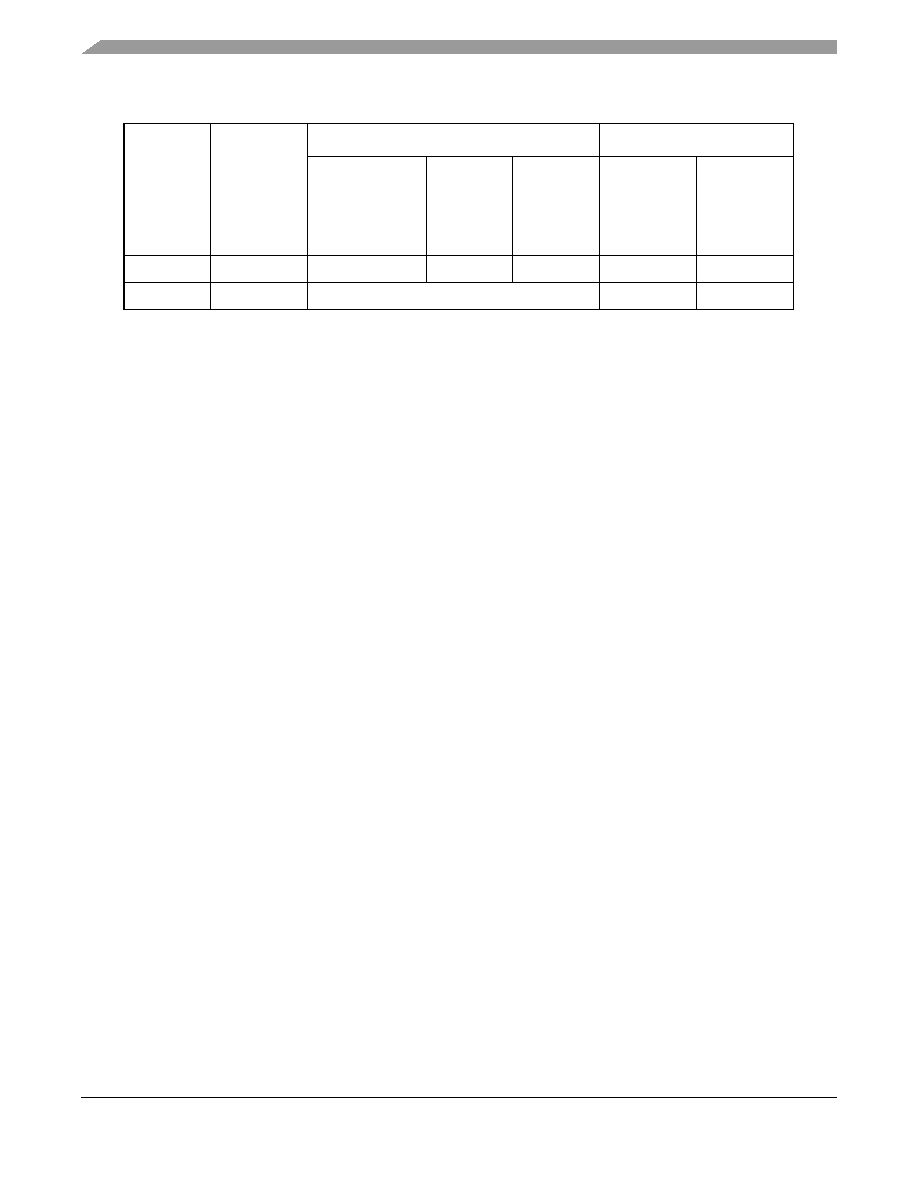
1E
11110
33
3
≠66
1,2
66≠132
231≠462
2 (2)
3.5 (2)
1F
11111
10
Not usable
Off
Off
Notes:
1.
Limited by maximum PCI input frequency (66 MHz).
2.
Limited by maximum memory interface operating frequency (133 MHz).
3.
Limited by minimum memory VCO frequency (132 MHz).
4.
Limited due to maximum memory VCO frequency (372 MHz).
5.
Limited by maximum CPU operating frequency (466 MHz).
6.
Limited by minimum CPU VCO frequency (360 MHz).
7.
Limited by maximum CPU VCO frequency (932 MHz).
8.
Limited by minimum CPU operating frequency (100 MHz).
9.
Limited by minimum memory bus frequency (50 MHz).
10. In clock off mode, no clocking occurs inside the MPC8245 regardless of the PCI_SYNC_IN input.
11. Range values are shown rounded down to the nearest whole number (decimal place accuracy removed) for
clarity.
12. PLL_CFG[0:4] settings not listed are reserved.
13. Multiplier ratios for this PLL_CFG[0:4] setting are different from the MPC8240 and are not
backwards-compatible.
14. PCI_SYNC_IN range for this PLL_CFG[0:4] setting is different from the MPC8240 and may not be fully
backwards-compatible.
15. Bits 7≠4 of register offset <0xE2> contain the PLL_CFG[0:4] setting value.
16. In PLL bypass mode, the PCI_SYNC_IN input signal clocks the internal processor directly, the peripheral
logic PLL is disabled, and the bus mode is set for 1:1 (PCI:Mem) mode operation. This mode is intended for
hardware modeling support. The AC timing specifications given in this document do not apply in the PLL
bypass mode.
17. In dual PLL bypass mode, the PCI_SYNC_IN input signal clocks the internal peripheral logic directly, the
peripheral logic PLL is disabled, and the bus mode is set for 1:1 (PCI_SYNC_IN:Mem) mode operation. In
this mode, the OSC_IN input signal clocks the internal processor directly in 1:1 (OSC_IN:CPU) mode
operation, and the processor PLL is disabled. The PCI_SYNC_IN and OSC_IN input clocks must be
externally synchronized. This mode is intended for hardware modeling support. The AC timing specifications
given in this document do not apply in the dual PLL bypass mode.
Table 19. PLL Configurations for the 466-MHz Part Offering (continued)
Ref
PLL_CFG
[0:4]
11,14,15
466-MHz Part
9
Multipliers
PCI Clock Input
(PCI_SYNC_IN)
Range
1
(MHz)
Periph
Logic/Mem
Bus Clock
Range
(MHz)
CPU Clock
Range
(MHz)
PCI-to-Mem
(Mem VCO)
Mem-to-CPU
(CPU VCO)
MPC8245 Part Number Specification for the MPC8245ARZUnnnX Series, Rev. 2
Freescale Semiconductor
15
Ordering Information
9
Ordering Information
Ordering information for the parts covered in this document is provided in
Section 9.1, "Part Numbers Fully
Addressed by This Document
."
Section 9.2, "Part Marking
," addresses the marking specifications.
9.1
Part Numbers Fully Addressed by This Document
Table 21
provides the ordering information for the MPC8245 parts described herein. Note that the individual part
numbers correspond to a maximum processor core frequency.
9.2 Part Marking
Parts are marked as in the example shown in
Figure 33
.
Figure 33. Freescale Part Marking for TBGA Device
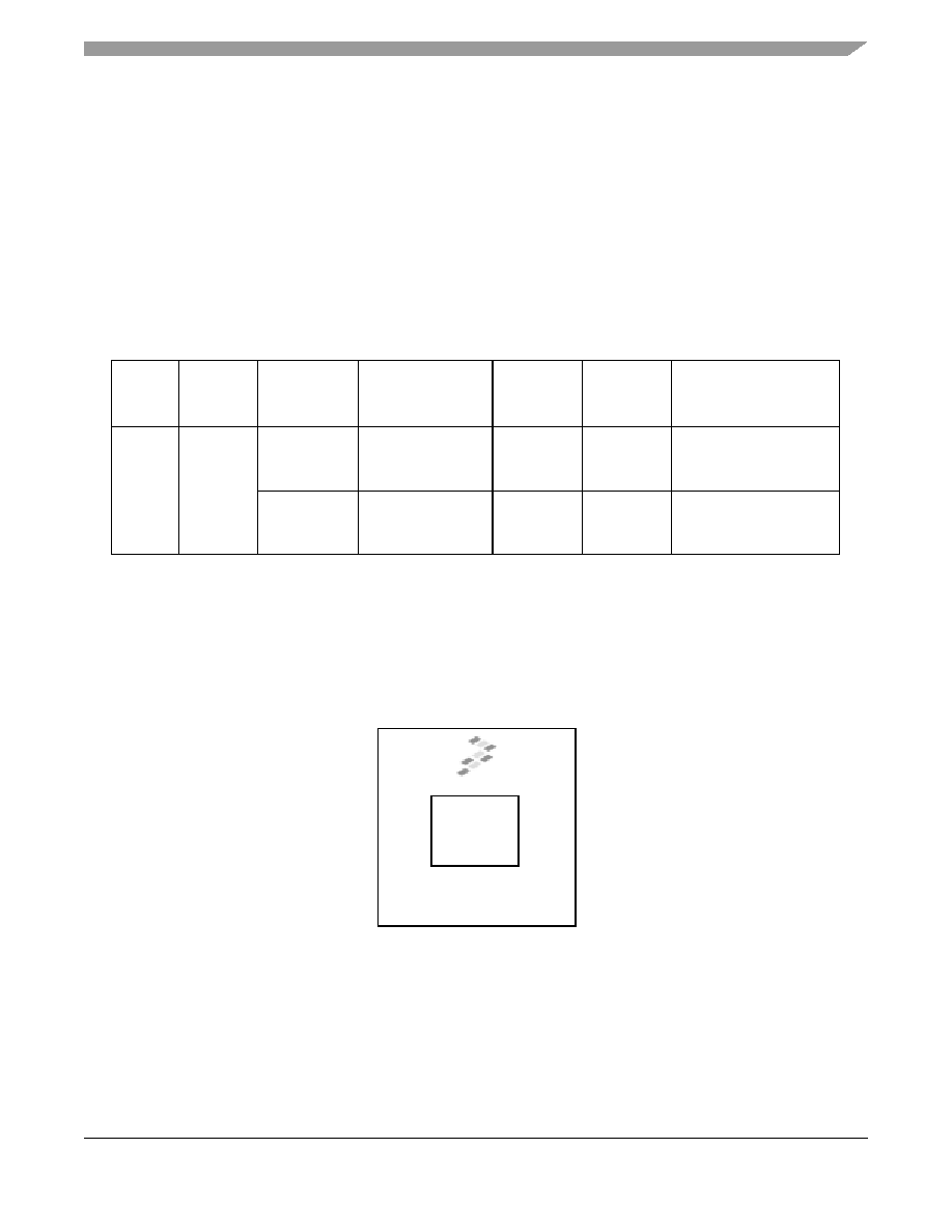
Table 21. Part Numbering Nomenclature
MPC
nnnn
X
(1)
Notes:
1. Note that on the standard `L' specification, the process descriptor is not added because it is the standard size for
the part (35 angstrom). The 400- and 466-MHz parts marked with `A' follow a different process description
(29 angstrom), which is different from the 35-angstrom process on the 350-MHz and lower frequency parts.
R
xx
nnn
X
Product
Code
Part
Identifier
Process
Descriptor
Part
Specification
Package
Processor
Frequency
(MHz)
Revision Level
MPC
8245
--
R = Partial Spec.
2.1 V ± 100 mV
0
∞
to 85
∞
C
ZU = TBGA
400
Contact local Freescale
sales office
A =
29 Angstrom
R = Partial Spec.
2.1 V ± 100 mV
0
∞
to 85
∞
C
ZU = TBGA
400, 466
Contact local Freescale
sales office
Notes
:
MMMMMM is the 6-digit mask number.
ATWLYYWWA is the traceability code.
MPC8245AR
ZUnnnx
MMMMMM
ATWLYYWWA
8245
TBGA
MPC8245 Part Number Specification for the MPC8245ARZUnnnX Series, Rev. 2
16
Freescale Semiconductor
Document Revision History
Document Revision History
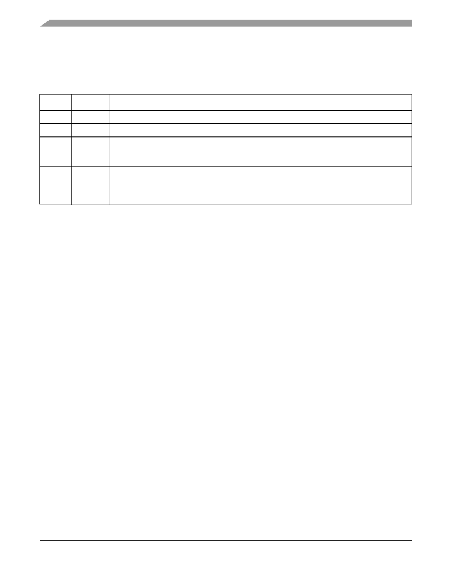
Table B
provides a revision history for this part number specification.
Table B Document Revision History
Rev. No.
Date
Substantive Change(s)
0
Original release.
0.1
Minor edit to part number.
1.0
∑ Added to list of parts covered by this document, including the non-A process identifier parts. Updated
Table A and Table 20.
∑ Nontechnical reformatting.
2
07/12/04
∑ Updated to Freescale template.
∑ Updated section numbers to accurately reflect hardware specifications sections.
∑ Changed junction temperature range in Table 1 to reflect range depicted in Table A (0
∞
to 85
∞
C).
∑ Added Section 4.3.1 to illustrate DLL locking graphs for 29 angstrom parts (400- and 466-MHz parts).

MPC8245 Part Number Specification for the MPC8245ARZUnnnX Series, Rev. 2
Freescale Semiconductor
17
Document Revision History
THIS PAGE INTENTIONALLY LEFT BLANK

MPC8245 Part Number Specification for the MPC8245ARZUnnnX Series, Rev. 2
18
Freescale Semiconductor
Document Revision History
THIS PAGE INTENTIONALLY LEFT BLANK

MPC8245 Part Number Specification for the MPC8245ARZUnnnX Series, Rev. 2
Freescale Semiconductor
19
Document Revision History
THIS PAGE INTENTIONALLY LEFT BLANK

How to Reach Us:
USA/Europe/Locations Not Listed:
Freescale Semiconductor
Literature Distribution Center
P.O. Box 5405,
Denver, Colorado 80217
1-480-768-2130
(800) 521-6274
Japan:
Freescale Semiconductor Japan Ltd.
Technical Information Center
3-20-1, Minami-Azabu, Minato-ku
Tokyo 106-8573, Japan
81-3-3440-3569
Asia/Pacific:
Freescale Semiconductor Hong Kong Ltd.
2 Dai King Street
Tai Po Industrial Estate
Tai Po, N.T. Hong Kong
852-26668334
Home Page:
www.freescale.com
Information in this document is provided solely to enable system and software implementers to use
Freescale Semiconductor products. There are no express or implied copyright licenses granted
hereunder to design or fabricate any integrated circuits or integrated circuits based on the information
in this document.
Freescale Semiconductor reserves the right to make changes without further notice to any products
herein. Freescale Semiconductor makes no warranty, representation or guarantee regarding the
suitability of its products for any particular purpose, nor does Freescale Semiconductor assume any
liability arising out of the application or use of any product or circuit, and specifically disclaims any
and all liability, including without limitation consequential or incidental damages. "Typical" parameters
which may be provided in Freescale Semiconductor data sheets and/or specifications can and do
vary in different applications and actual performance may vary over time. All operating parameters,
including "Typicals" must be validated for each customer application by customer's technical experts.
Freescale Semiconductor does not convey any license under its patent rights nor the rights of others.
Freescale Semiconductor products are not designed, intended, or authorized for use as components
in systems intended for surgical implant into the body, or other applications intended to support or
sustain life, or for any other application in which the failure of the Freescale Semiconductor product
could create a situation where personal injury or death may occur. Should Buyer purchase or use
Freescale Semiconductor products for any such unintended or unauthorized application, Buyer shall
indemnify and hold Freescale Semiconductor and its officers, employees, subsidiaries, affiliates, and
distributors harmless against all claims, costs, damages, and expenses, and reasonable attorney
fees arising out of, directly or indirectly, any claim of personal injury or death associated with such
unintended or unauthorized use, even if such claim alleges that Freescale Semiconductor was
negligent regarding the design or manufacture of the part.
Learn More: For more information about Freescale Semiconductor products, please visit
www.freescale.com
MPC8245ARZUPNS
Rev. 2
07/2004
FreescaleTM and the Freescale logo are trademarks of Freescale Semiconductor, Inc. The described
product contains a PowerPC processor core. The PowerPC name is a trademark of IBM Corp. and
used under license. All other product or service names are the property of their respective owners.
© Freescale Semiconductor, Inc. 2004.