
25 Locust St, Haverhill, Massachusetts 01830 ∑ Tel: 800/252-7074, 978/374-0761 ∑ FAX: 978/521-1839
e-mail: sales@freqdev.com ∑ Web Address: http://www.freqdev.com
1.0 Hz to 100 kHz
Fixed Frequency
D76 & DP76 Series
32 Pin DIP
6-Pole Filters
Available Low-Pass Models:
. . . . . . . . . . . . . . . .
D76L6B
6-pole Butterworth . . . . . . . . . . . . . . .2
DP76L6B 6-pole Butterworth (Low Power) . . . . .2
D76L6L
6-pole Bessel . . . . . . . . . . . . . . . . . . .2
DP76L6L 6-pole Bessel (Low Power) . . . . . . . .2
Available High-Pass Models:
D76H6B 6-pole Butterworth . . . . . . . . . . . . . . .2
General Specifications:
Pin-out/package data & ordering information . . . .3
Description
The D76 and DP76 Series of low-power, fixed-
frequency, linear active filters are high performance,
6-pole filters in a compact package. These
Butterworth and Bessel low-pass and Butterworth
high-pass filters (D76 only) combine linear active
filter design with the space savings of a 32-pin dual
in-line package (DIP). Each model comes factory
tuned to a user-specified corner frequency between
1 Hz and 100 kHz (DP76, 1 Hz to 5kHz). These fully
self-contained units require no external components
or adjustments and operate with dynamic input
voltage range from non-critical ±5V to ±18V power
supplies.
Applications
∑ Anti-alias filtering
∑ Vibration & shock analysis
∑ Automatic test equipment
∑ Aerospace, navigation and sonar
∑ Communication systems
∑ Medical electronics
∑ Sound and vibration testing
∑ Noise elimination
∑ Process control
Features/Benefits:
∑ Low cost solution for low frequency signal
conditioning
∑ Compact DIP design minimizes board space
requirements
∑ Plug-in ready-to-use, reducing engineering design
and manufacturing time
∑ Factory tuned, no external clocks or adjustments
needed saving time and labor of other discrete
assembly solutions
∑ Low harmonic distortion and wide signal-to-noise
ratio to 12 bit resolution
1
Fixed Frequency
D76 & DP76 Series
6-Pole
Low-Pass and High-Pass Filters
25 Locust St, Haverhill, Massachusetts 01830 ∑ Tel: 800/252-7074, 978/374-0761 ∑ FAX: 978/521-1839
e-mail: sales@freqdev.com ∑ Web Address: http://www.freqdev.com
2
Model
D76L6B & DP76L6B
D76L6L & DP76L6L
Model
D76H6B
Product Specifications
Low-Pass
Low-Pass
High-Pass
Transfer Function
6-Pole, Butterworth
6-Pole, Bessel
Transfer Function
6-Pole, Butterworth,
Size
Size
D76 1.00 Hz to 1.00 kHz 1.8" x 0.8" x 0.5"
1.8" x 0.8" x 0.5"
D76
1.00 Hz to 1.00 kHz
1.8" x 0.8" x 0.5"
D76 1.01 kHz to 100 kHz 1.8" x 0.8" x 0.3"
1.8" x 0.8" x 0.3"
D76
1.01 kHz to 100 kHz 1.8" x 0.8" x 0.3"
DP761.00 Hz to 5.00 kHz 1.8" x 0.8" x 0.5"
1.8" x 0.8" x 0.5"
Range f
c
Range f
c
D76
1 Hz to 100 kHz
1 Hz to 100 kHz
D76
1 Hz to 100 kHz
DP76
1 Hz to 5 kHz
1 Hz to 5 kHz
Theoretical Transfer
Appendix A
Appendix A
Theoretical Transfer
Appendix A
Characteristics
Page 8
Page 3
Characteristics
Page 28
Passband Ripple
0.0 dB
0.0 dB
Passband Ripple
0.0 dB
(theoretical)
(theoretical)
DC Voltage Gain
0 ± 0.1 dB typ.
0 ± 0.1 dB typ.
Voltage Gain
0 ± 0.1 dB to 100 kHz
(non-inverting)
(non-inverting)
Stopband
Stopband
Attenuation Rate
36 dB/octave
36 dB/octave
Attenuation Rate
36 dB/octave
Power Bandwidth
120 kHz
Small Signal Bandwidth
(-6 dB) 1 MHz
Cutoff Frequency
f
c
± 2% max.
f
c
± 2% max.
Cutoff Frequency
f
c
± 2% max.
Stability
± 0.03% /∞C
± 0.03% /∞C
Stability
± 0.03% /∞C
Amplitude
-3 dB
-3 dB
Amplitude
-3 dB
Phase
-270∞
-155∞
Phase
-270∞
Filter Attenuation
0.29 dB 0.80 f
c
1.89 dB 0.80 f
c
Filter Attenuation
80.0 dB .21 f
c
(theoretical)
3.01 dB 1.00 f
c
3.01 dB 1.00 f
c
(theoretical)
60.0 dB .32 f
c
60.0 dB 3.16 f
c
60.0 dB 5.41 f
c
3.01 dB 1.00 f
c
80.0 dB 4.64 f
c
80.0 dB 7.99 f
c
0.00 dB 2.50 f
c
Total Harmonic
Total Harmonic
Distortion @ 1 kHz
Distortion @ 1 kHz
D76
<-70 dB
<-70 dB
D76
<-70 dB
DP76
<-70 dB
<-70 dB
Wide Band Noise
200
mVrms typ.
200
mVrms typ.
Wide Band Noise
400
mVrms typ.
(5 Hz - 2 MHz)
(5 Hz - 2 MHz)
Narrow Band Noise
50
mVrms typ.
50
mVrms typ.
Narrow Band Noise
100
mVrms typ.
(20 Hz - 100 kHz)
(20 Hz - 100 kHz)
Filter Mounting
Filter Mounting
Assembly
FMA-01A
FMA-01A
Assembly
FMA-01A
Specification
(25∞C and Vs ± 15 Vdc)
D76 & DP76 Series
Pin-Out and Package Data
Ordering Information
We hope the information given here will be helpful. The information is based on data and our best knowledge, and we consider the information to be true and accurate. Please read all statements,
recommendations or suggestions herein in conjunction with our conditions of sale which apply to all goods supplied by us. We assume no responsibility for the use of these statements,
recommendations or suggestions, nor do we intend them as a recommendation for any use which would infringe any patent or copyright.
IN-00D76-00
Filter Type
L - Low Pass
H - High Pass
Analog Input Characteristics
1
Impedance
10 k
W min.
Voltage Range
± 10 Vpeak
Max. Safe Voltage
± Vs
Analog Output Characteristics
Impedance
1
W
Linear Operating Range ± 10 V
Maximum Current
2
D76
± 10 mA
DP76
± 5 mA
Offset Voltage
20 mV max.
1
3 mV typ.
Offset Temp. Coeff.
20
mV / ∞C typ.
Power Supply (±V)
Rated Voltage
± 15 Vdc
Operating Range
± 5 to ± 18 Vdc
Maximum Safe Voltage
± 18 Vdc
Quiescent Current D76
9 mA max.
6.5 mA typ.
Quiescent Current DP76
2.0 mA max.
1.2 mA typ.
Temperature
Operating
-
0 to + 70 ∞C
Storage
- 25 to + 85 ∞C
Notes:
1. Input and output signal voltage referenced to
supply common.
2. Output is short circuit protected to common. DO
NOT CONNECT TO ±Vs.
Ordering Information
3. How to Specify Corner Frequency:
Corner frequencies are specified by attaching a three digit frequency designator to the
basic model number. Corner frequencies can range from 1 Hz to 100 kHz.
D76L6B-849 Hz
- 3 dB Corner Frequency
3
e.g., 849 Hz
2.50 kHz
33.3 kHz
Transfer Function
B - Butterworth
L - Bessel
Power Level
D ≠ Standard Power
DP ≠ Low Power
25 Locust St, Haverhill, Massachusetts 01830 ∑ Tel: 800/252-7074, 978/374-0761 ∑ FAX: 978/521-1839
e-mail: sales@freqdev.com ∑ Web Address: http://www.freqdev.com
3
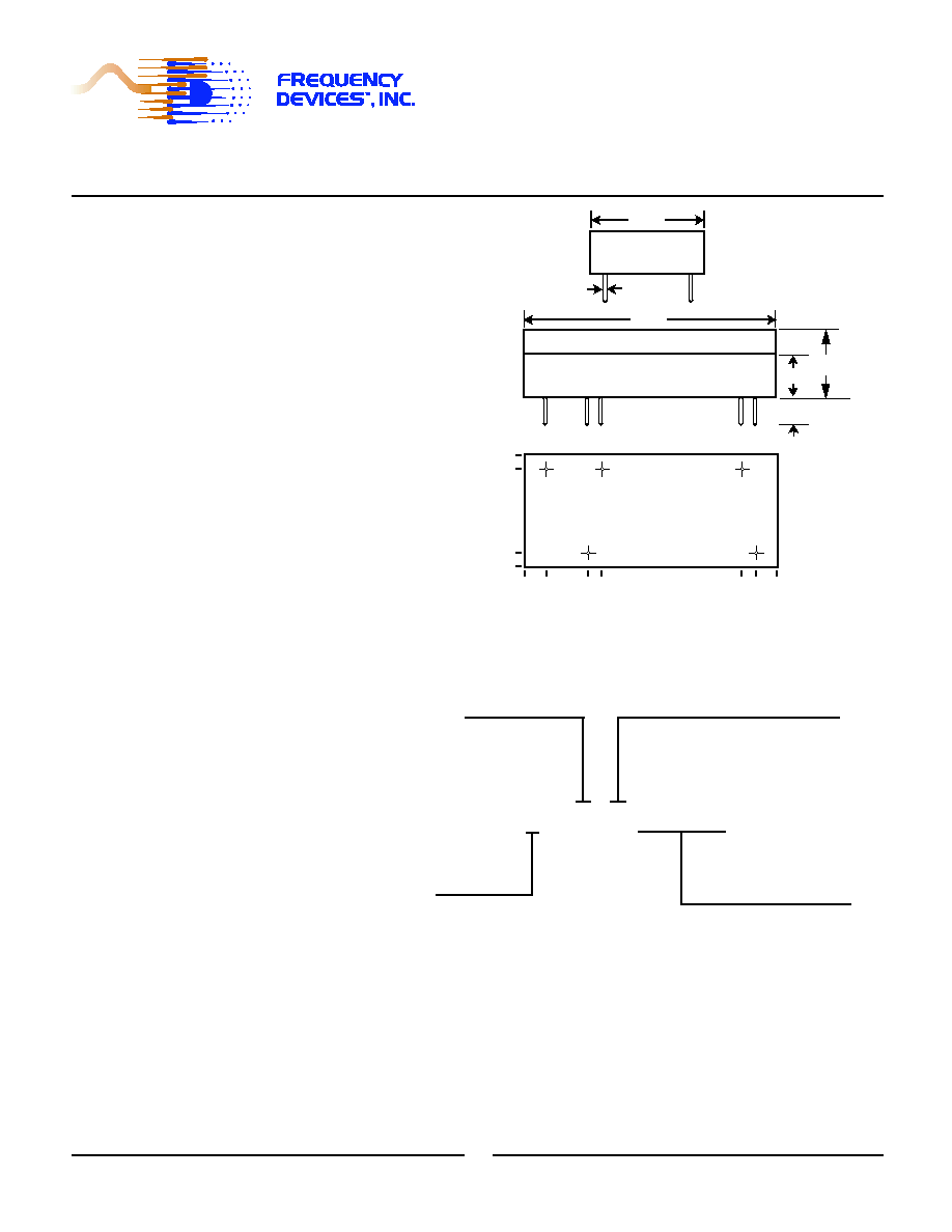
Side View
0.80
0.025 dia.
All dimensions are in inches
All case dimensions
± 0.01"
Bottom View
+VS
OUT
-VS
IN
GND
0.80
0.70
0.10
0.00
0.00
0.15
0.45
0.55
1.55
1.65
1.80
0.15 (min)
Front View
0.30
1.80
0.50
Filter Mounting Assembly-See FMA-01A

Low-Pass
6-Pole
Appendix A
Bessel
3
25 Locust St., Haverhill, Massachusetts 01830
Tel :800/252-7074, 978/374-0761
FAX:978/521-1839
e-mail: sales@freqdev.com
Web Address: http://www.freqdev.com
Fax on Demand: 978/521-5178
Normalized Frequency(f/fc)
Amp (dB)
Normalized Time (1/f sec)
Dela
y (sec)
Normalized Time (1/f sec)
Step Response (V/V)
Frequency Response
Delay (Normalized)
Step Response
0.1
1.0
10.0
2 3 4 5678
2 3 4 567
-100
-80
-60
-40
-20
0
0.1
1.0
2
3
4 5 6 7 8 9
0.0
0.5
1.0
1.5
0.15
0
1
2
3
4
5
-0.0
-0.2
0.2
0.4
0.6
0.8
1.0
1.2
(sec)
Theoretical Transfer Characteristics
1
0.00
0.10
0.20
0.30
0.40
0.50
0.60
0.70
0.80
0.85
0.90
0.95
1.00
1.10
1.20
1.30
1.40
1.50
1.60
1.70
1.80
1.90
2.00
2.25
2.50
2.75
3.00
3.25
3.50
4.00
5.00
6.00
7.00
8.00
9.00
10.0
1.Normalized Group Delay:
The above delay data is normalized to a corner frequency
of 1.0Hz.The actual delay is the normalized delay divided
by the actual corner frequency (fc).
Actual Delay =
Normalized Delay
Actual Corner Frequency (fc) in Hz
f/fc
(Hz)
Amp
(dB)
Phase
(deg)
Delay
-65.2
-73.2
-80.1
-86.2
-91.6
-30.7
-34.5
-38.1
-44.7
-55.9
-12.6
-14.2
-18.3
-22.6
-26.7
-6.23
-7.29
-8.46
-9.74
-11.1
-465
-476
-484
-490
-495
-385
-398
-408
-426
-449
-287
-300
-328
-351
-369
-216
-232
-246
-261
-275
.036
.026
.020
.015
.013
.156
.131
.111
.083
.052
.357
.335
.279
.228
187
.422
.416
.401
.393
.376
-2.70
-3.01
-3.68
-4.44
-5.29
-1.05
-1.44
-1.89
-2.15
-2.42
0.00
-0.029
-0.116
-0.261
-0.465
-0.728
-147
-155
-170
-186
-201
-92.9
-108
-124
-132
-139
0.00
-15.5
-31.0
-46.5
-62.0
-77.4
.430
.430
.429
.428
.426
.430
.430
.430
.430
.430
.430
.430
.430
.430
.430
.430

Low-Pass
6-Pole
Appendix A
Butterworth
8
25 Locust St., Haverhill, Massachusetts 01830
Tel :800/252-7074, 978/374-0761
FAX:978/521-1839
e-mail: sales@freqdev.com
Web Address: http://www.freqdev.com
Fax on Demand: 978/521-5178
Normalized Frequency(f/fc)
Amp (dB)
Normalized Time (1/f sec)
Dela
y (sec)
Normalized Time (1/f sec)
Step Response (V/V)
Frequency Response
Delay (Normalized)
Step Response
0.1
1.0
10.0
2
3 4 5 6 78
2
3 4 5 6 7
-100
-80
-60
-40
-20
0
0.1
1.0
2
3
4
5 6 7 8 9
0.0
1.0
2.0
1.5
0.15
0
1
2
3
4
5
-0.0
0.2
0.4
0.6
0.8
1.0
1.2
(sec)
Theoretical Transfer Characteristics
1
0.00
0.10
0.20
0.30
0.40
0.50
0.60
0.70
0.80
0.85
0.90
0.95
1.00
1.10
1.20
1.30
1.40
1.50
1.60
1.70
1.80
1.90
2.00
2.25
2.50
2.75
3.00
3.25
3.50
4.00
5.00
6.00
7.00
8.00
9.00
10.0
1.Normalized Group Delay:
The above delay data is normalized to a corner frequency
of 1.0Hz.The actual delay is the normalized delay divided
by the actual corner frequency (fc).
Actual Delay =
Normalized Delay
Actual Corner Frequency (fc) in Hz
f/fc
(Hz)
Amp
(dB)
Phase
(deg)
Delay
-93.4
-101
-108
-115
-120
-57.3
-61.4
-65.3
-72.2
-83.9
-33.5
-36.1
-42.3
-47.8
-52.7
-503
-508
-512
-515
-518
-465
-471
-476
-484
-496
-419
-425
-439
-450
-458
.017
.012
.0097
.0076
.0062
.071
.060
.052
.039
.025
.193
.171
.132
.105
.086
-17.6
-21.2
-24.5
-27.7
-30.6
-1.88
-3.01
-6.17
-9.96
-13.9
-0.009
-0.060
-0.289
-0.578
-1.080
0.00
0.00
0.00
0.00
0.00
-0.001
-368
-382
-393
-403
-412
-252
-270
-304
-331
-352
-140
-167
-198
-215
-233
0.00
-22.2
-44.5
-67.2
-90.4
-115
.417
.345
.291
.251
.219
1.03
1.00
.845
.660
.518
.731
.803
.911
.970
1.02
.615
.617
.624
.637
.656
.685