25 Locust St, Haverhill, Massachusetts 01830 ∑ Tel: 800/252-7074, 978/374-0761 ∑ FAX: 978/521-1839
e-mail: sales@freqdev.com ∑ Web Address: http://www.freqdev.com
1.0 Hz to 102.4 kHz
8-Bit Programmable
D828 Series
2" x 2"
Differential Input
8-Pole Filters
Description
The D828 Series are digitally programmable low-
pass and high-pass active filters with differential
input that are tunable over a 256:1 frequency range.
D828 filters are available with any one of five
standard factory-set tuning ranges or 8-bit custom
ranges from 1.0 Hz to 102.4 kHz. These units con-
tain 8 CMOS logic inputs.
All D828 Series models are convenient, low profile,
easy to use fully finished filters which require no
external components or adjustments. They feature
low harmonic distortion, and near theoretical phase
and amplitude characteristics. D828 filters operate
from non-critical Ī 12 to Ī 18 Vdc power supplies,
have a 10 k
(min.) input and a 10 (max.) output
impedance.
Features/Benefits:
∑
Compact 2" x 2" design minimizes board space
requirements.
∑
Low harmonic distortion and wide signal-to-noise
ratio to 16 bit resolution.
∑
Digitally programmable corner frequency allows
selecting cut-off frequencies specific to each
application.
∑
Plug-in ready-to-use, reducing engineering
design and manufacturing cycle time.
∑ Factory-set tuning range, no external clocks or
adjustments needed
∑ Broad range of transfer characteristics and corner
frequencies to meet a wide range of applications.
Applications
∑ Anti-alias filtering
∑ Data acquisition systems
∑ Communication systems and electronics
∑ Medical electronics equipment and research
∑ Aerospace, navigation and sonar applications
∑
Sound and vibration testing
∑ Real and compressed time data analysis
∑ Noise elimination
∑ Signal reconstruction
Programmable Specifications:
. . . . . . . . . . . . .
Page
Digital Tuning & Control . . . . . . . . . . . . . . . . . . . . . 2
Available Low-Pass Models:
. . . . . . . . . . . . . . . . . .
D828
L8B
8-pole Butterworth . . . . . . . . . . . . . . . 3
D828
L8E
8-pole, 6 zero elliptic, 1.77 (-80dB) . . . 3
D828
L8EX 8-pole, 6 zero elliptic, 1.56 (-80dB) . . . 3
D828
L8EY 8-pole, 6 zero elliptic, 2.00 (-100dB) . . 3
D828
L8L
8-pole Bessel . . . . . . . . . . . . . . . . . . . 4
D828
L8D60 8-pole constant delay (-60dB). . . . . . . 4
D828
L8D80 8-pole constant delay (-80dB). . . . . . . 4
D828
L8D10 8-pole constant delay (-100dB) . . . . . . 4
Available High-Pass Models:
. . . . . . . . . . . . . . . . . .
D828
H8B
8-pole Butterworth . . . . . . . . . . . . . . . . 5
D828
H8E
8-pole, 6 zero elliptic, 1.77 (-80dB) . . . 5
D828
H8EX 8-pole, 6 zero elliptic, 1.56 (-80dB) . . . 5
D828H8EY
8-pole, 6 zero elliptic, 2.00 (-100dB) . . . 5
General Specifications:
Ordering information . . . . . . . . . . . . . . . . . . . . . . . . 6
Pin-out/package data . . . . . . . . . . . . . . . . . . . . . . . . 6
8-Bit Programmable Filters
D828 Series
Digital Tuning &
Control Characteristics
25 Locust St, Haverhill, Massachusetts 01830 ∑ Tel: 800/252-7074, 978/374-0761 ∑ FAX: 978/521-1839
e-mail: sales@freqdev.com ∑ Web Address: http://www.freqdev.com
2
Digital Tuning Characteristics
The digital tuning interface circuits are a parallel set of eight
(8) 4053 CMOS switches which accept CMOS compatible
inputs for the eight tuning bits (D
0
- D
7
).
Filter tuning follows the tuning equation given below:
f
c
= ( f
max
/256 ) [ 1 + D
7
x 2
7
+ D
6
x 2
6
+ D
5
x 2
5
+ D
4
x 2
4
+
D
3
x 2
3
+ D
2
x 2
2
+ D
1
x 2
1
+ D
0
x 2
0
]
where D
1
- D
7
= "0" or "1", and
f
max
= Maximum tuning frequency;
f
c
= corner frequency;
Minimum tunable frequency = f
max
/256 (D
0
thru D
7
= 0);
Minimum frequency step (Resolution) = f
max
/256
Data Input Specifications
Input Data Levels
(CMOS Logic)
Input Voltage (Vs = 15 Vdc)
Low Level In
0 Vdc min.
4 Vdc max.
High Level In
11 Vdc min.
15 Vdc max.
Input Current
High Level In
- 10
-5
ĶA typ.
-1
ĶA max.
.
Low Level In
+10
-5
ĶA typ
.
+1
ĶA max.
Input Capacitance
5 pF typ
7.5 pF max.
Input Data Format
Frequency Select Bits
Positive Logic
Logic "1" = +Vs
Logic "0" = Gnd
Bit Weighting
(Binary-Coded)
D
0
LSB (least significant bit)
D
7
MSB (most significant bit)
Frequency Range
256 : 1, Binary Weighted
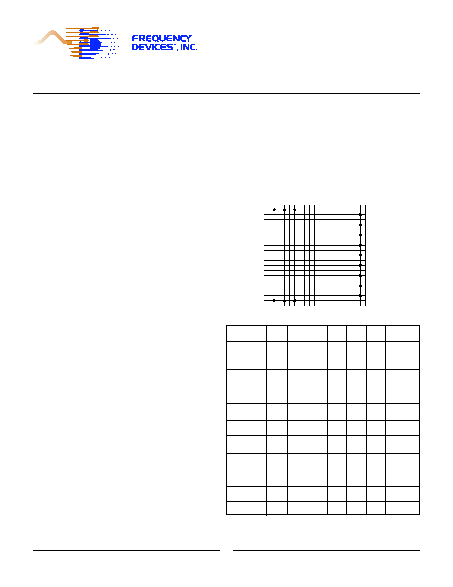
Pin-Out Key
IN
Analog Input Signal
D
7
Tuning Bit 7 (MSB)
OUT Analog Output Signal
D
6
Tuning Bit 6
GND Power and Signal Return
D
5
Tuning Bit 5
+Vs
Supply Voltage, Positive
D
4
Tuning Bit 4
-Vs
Supply Voltage, Negative
D
3
Tuning Bit 3
Os
Offset Adjustment
D
2
Tuning Bit 2
D
1
Tuning Bit 1
D
0
Tuning Bit 0 (LSB)
MSB
---
---
---
---
---
---
LSB
Bit
Weight
2
7
2
6
2
5
2
4
2
3
2
2
2
1
2
0
fc
Corner
Frequency
D
7
D
6
D
5
D
4
D
3
D
2
D
1
D
0
0
0
0
0
0
0
0
0
f
max
/256
0
0
0
0
0
0
0
1
f
max
/128
0
0
0
0
0
0
1
1
f
max
/64
0
0
0
0
0
1
1
1
f
max
/32
0
0
0
0
1
1
1
1
f
max
/16
0
0
0
1
1
1
1
1
f
max
/8
0
0
1
1
1
1
1
1
f
max
/4
0
1
1
1
1
1
1
1
f
max
/2
1
1
1
1
1
1
1
1
fmax
+Vs
OUT
-Vs
D
D
D
D
GND
D
D
D
D
-IN
2.00
Os
4
5
3
2
1
0
6
7
4
+IN