NOTE: Standard Specifications for product indicated in
color
14
Dimensions:
I n c h e s
(mm)
MARKING: See Page 52, Format A
MARKING: See Page 52, Format A
Frequency (MHz)
Mode Max. ESR (Ohms)
OPERATION MODE AND ESR TABLE
3.5 - 4.9
Fundamental
200
5.0 - 5.9 Fundamental 150
6.0 - 7.9 Fundamental
120
8.0 - 8.9 Fundamental
90
9.0 - 9.9
Fundamental
80
10.0 - 14.9
Fundamental
70
15.0 - 15.9
Fundamental
60
16.0 - 29.9
Fundamental
50
30.0 - 49.9
3rd Overtone
80
50.0 - 70.0
3rd Overtone
80
J-LEAD PLASTIC SMD
Parameter
Specification
SPECIFICATIONS
SPECIFICATIONS
FMXM
FMXM JS
JS 11 18
18 H
H JJ A
A - - XX.XXXXXXM
XX.XXXXXXM - - CM
CM
H - Ī 30 ppm
I - Ī 40 ppm
J - Ī 50 ppm
K - Ī 100 ppm
X - Custom
15302 Bolsa Chica St., Huntington Beach, CA. 92649
Tel.: 714-892-3234 Fax: 714-890-1832
E-mail: sales@frequencymanagement.com
www.frequencymanagement.com
18 - Standard (pF)
00 - Series
nn - Custom (pF)
1 - Fundamental
3 - 3rd Overtone
PART NUMBERING SYSTEM
PART NUMBERING SYSTEM
J - Ī 50 ppm
K - Ī 100 ppm
X - Custom
All specifications subject to change without notice.
Mode
Load Cap. (CL)
MicroP Crystal
Product Family
Cal. Tol. @
25įC
Temp. Tol.
Frequency (MHz)
J-Lead SMD
Package
1-800-800-XTAL
(9825)
T R - Tape & Reel
P D - Parameter Data
T D - Temp. Data
TG - Temp. Grading
CM - Custom Mark
BLANK - None Req'd.
Options
0.063
(1.60)
0.370
(9.40)
0.552
(14.02)
MAX.
R e c o m m e n d e d
Land Pattern
0.040
(1.02)
0.063
(1.60)
0.060
(1.52)
1
4
0.230
(5.84)
4
3
2
1
0.200
(5.08)
MAX.
0.118
(3.00)
MAX.
0.160
(4.06)
0.100
(2.54)
0.200
(5.08)
MAX.
2
3
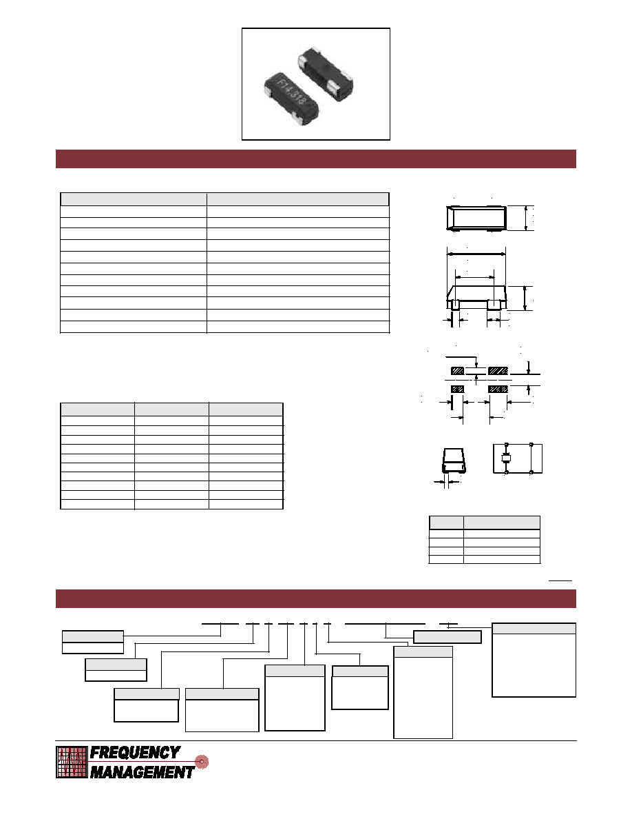
FMXMJS
SERIES
Microprocessor Crystals
J-LEAD PLASTIC SMD
∑
J - Lead Surface Mount
∑
Tape & Reel
∑
Low Cost
Frequency Range
3.57 to 70.0 MHz
Operation Mode
See Operation Mode and ESR Table
Load Capacitance (CL)
18 pF Std., 8 to 60 pF and Series available
Frequency Tolerance
Ī30 ppm @ 25įC Std. (See Cal. Tol. for Options)
Temperature Tolerance
Ī50 ppm Std. (See Temp. Tol. for Options)
Operating Temperature
0 to +70įC Std. (See Temp. Range for Options)
Storage Temperature
-40 to +85įC
Equivalent Series Resistance (ESR)
See Operation Mode and ESR Table
Shunt Capacitance (C0)
7 pF max.
Drive Level
50 uW typical, 1 mW max.
Aging @ 25įC
Ī5 ppm per year max.
1 Crystal
2 Ground
3 Ground
4 Crystal
Pin Function
PIN FUNCTION TABLE
MARKING: See Page 56, Format F
MARKING: See Page 56, Format F
A 0 to 70 įC
B -20 to 70 įC
C -40 to 85 įC
D -10 to 50 įC
E -10 to 60 įC
F
-30 to 60 įC
J
0 to 50 įC
X - Custom
Temp. Range