6R1MBi100P-160
Diode Module
Diode Module with Brake
Diode:1600V / 100A, IGBT:1400A/75A
Features
∑ Compact Package
∑ P.C. Board Mount Module
∑ Converter Diode Bridge Dynamic Brake Circuit
Applications
∑ Inverter for Motor Drive
∑ AC and DC Servo Drive Amplifier
∑ Uninterruptible Power Supply
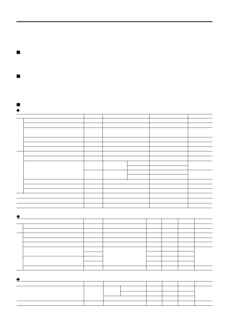
Maximum ratings and characteristics
Absolute maximum ratings (Tc=25∞C unless without specified)
Item Symbol Condition Rating Unit
Repetitive peak reverse voltage
Non-repetitive peak reverse voltage
Average output current
One cycle surge current
I
2
t
Operation junction temperature
Collector-Emitter voltage
Gate-Emitter voltage
Collector current
Collector power disspation
Repetitive peak reverse voltage
Operation junction temperature
Brake
Converte
Storage junction temperature
Isolation voltage
Mounting screw torque
V
RRM
V
RSM
I
O
I
FSM
I
2
t
T
j
V
CES
V
GES
I
C
I
CP
P
C
V
RRM
T
j
T
stg
V
iso
50Hz/60Hz sine wave
Tc=110∞C
From rated load
From rated load
DC Tc=25∞C
Tc=75∞C
1ms Tc=25∞C
Tc=75∞C
1 device
AC : 1 minute
M5 screw
1600
1760
100
1000
4000
-40 to +125
1400
±20
75
50
150
100
360
1400
+150
-40 to +125
2500
2.0 to 2.5
V
V
A
A
A
2
s
∞C
V
V
A
A
W
V
∞C
∞C
V
N∑m
Fofward voltage
Reverse current
Zero gate voltage Collector current
Gate-Emitter leakage current
Collector-Emitter saturation voltage
Turn-on time
Turn-off time
Reverse current
Electrical characteristics (Tj=25∞C unless otherwise specified)
Item Symbol Condition Min. Typ. Max. Unit
Thermal characteristics
Item Symbol Condition Min. Typ. Max. Unit
Thermal resistance
Thermal Resistance(Case to fine)
V
FM
I
RRM
I
CES
I
GES
V
CE(sat)
ton
tr
toff
tf
I
RRM
R
th(j-c)
R
th(c-f)
Tj=25∞C, I
FM
=100A
Tj=150∞C, V
R
=V
RRM
V
GE
=0V. V
CE
=1400V
V
CE
=0V. V
GE
=±20V
V
GE
=15V. I
C
=50A
Vcc=800V
Ic=50A
V
GE
=±15V
R
G
=25ohm
Converter Per total loss
Per each device
Brake IGBT (1 device)
with thermal compound
1.30
20
1.0
200
2.4
2.8
0.35
1.2
0.25
0.6
0.45
1.0
0.08
0.3
1.0
0.14
0.84
0.55
0.08
V
mA
mA
nA
V
µs
mA
∞C/W
∞C/W
Brake Co.

6R1MBi100P-160
Diode Module
Forward Characteristics
0.5
0.6
0.7
0.8
0.9
1
1.1
1.2
1.3
1.4
0
10
20
30
40
50
60
70
80
90
100
F
o
r
w
ar
d C
u
r
r
e
n
t
V
F
(
V
)
Forward Current IF(A)
max
typ
150deg
25deg
O u tp u t C u r r e n t - T o ta l L o s s
0
5 0
1 0 0
1 5 0
2 0 0
2 5 0
3 0 0
0
5 0
1 0 0
1 5 0
O u tp i t C u r r e n t Io ( A )
Total Loss (W)
S u rg e C u rre n t
0
2 0 0
4 0 0
6 0 0
8 0 0
1 0 0 0
1 2 0 0
0 .0 1
0 .1
1
Peak Surge Current IFSM (A)
T i m
Tra nsie nt The rm a l Im p e d a nce
0.001
0.01
0.1
1
0.001
0.01
0.1
1
10
Zth(j-c)(deg.C/w)
Tim
e
[ B ra ke ] Tra nsie nt The rm a l Im p e d a nc e
0.01
0.1
1
10
0.001
0.01
0.1
1
10
Tim e (s e c)
Zth(j-c)(t) (deg.C/W)
IG BT
FW D
O u tp u t C u r r e n t - C a s e T e m p e r a tu r e
5 0
6 0
7 0
8 0
9 0
1 0 0
1 1 0
1 2 0
1 3 0
0
5 0
1 0 0
O u t p u t C u r r e n t Io ( A )
Case Tempreture Tc (deg.C)

6R1MBi100P-160
Diode Module
0
1
2
3
4
5
0
20
40
60
80
100
120
8V
10V
12V
15V
VGE= 20V
[ Brake ]
Collector current vs. Collector-Emitter voltage
Tj= 25∞C (typ.)
C
o
l
l
e
c
to
r
cur
r
e
n
t
:
Ic
[ A
]
Collector - Emitter voltage : VCE [ V ]
0
1
2
3
4
5
0
20
40
60
80
100
120
8V
10V
12V
15V
VGE= 20V
[ Brake ]
Collector current vs. Collector-Emitter voltage
Tj= 125∞C (typ.)
Collector - Emitter voltage : VCE [ V ]
C
o
l
l
e
c
to
r
cur
r
e
n
t
:
Ic
[ A
]
0
1
2
3
4
5
0
20
40
60
80
100
120
Tj= 25∞C
Tj= 125∞C
[ Brake ]
Collector current vs. Collector-Emitter voltage
VGE=15V (typ.)
Collector - Emitter voltage : VCE [ V ]
C
o
l
l
e
c
to
r
cur
r
e
n
t
:
Ic
[ A
]
5
10
15
20
25
0
2
4
6
8
10
Ic= 25A
Ic= 50A
Ic= 100A
[ Brake ]
Collector-Emitter voltage vs. Gate-Emitter voltage
Tj= 25∞C (typ.)
C
o
l
l
e
c
to
r
-
E
m
i
t
te
r
v
o
l
t
a
g
e
:
V
C
E
[ V
]
Gate - Emitter voltage : VGE [ V ]
0
5
10
15
20
25
30
35
100
1000
10000
20000
[ Brake ]
Capacitance vs. Collector-Emitter voltage (typ.)
VGE=0V, f= 1MHz, Tj= 25∞C
C
a
pa
ci
t
a
nc
e
:
C
i
e
s
,
Co
e
s
, Cr
e
s
[
pF
]
Collector - Emitter voltage : VCE [ V ]
Coes
Cres
Cies
0
100
200
300
400
500
0
200
400
600
800
1000
[ Brake ]
Dynamic Gate charge (typ.)
Vcc=800V, Ic=50A, Tj= 25∞C
Gate charge : Qg [ nC ]
C
o
l
l
e
c
to
r
-
E
m
i
t
te
r
v
o
l
t
a
g
e
:
V
C
E
[ V
]
0
5
10
15
20
25
Ga
te
-
E
m
i
t
t
e
r
v
o
l
t
a
g
e
:
V
G
E
[
V
]
