s
FEATURES
q
Extremely low profile and light weight
--Height: 5 mm
--Weight: approximately 1.2 g
q
UL, CSA recognized
q
Conforms to FCC rules and regulations part 68
--Surge strength 1,500 V
q
High reliability--bifurcated contacts
q
Wide operating range
q
DIL pitch terminals
q
Plastic sealed type
q
Latching version available
(a)
Series Name
A : A Series
(b)
Operation Function
Nil : Standard type
L : Latching type
(c)
Number of Coil
Nil : Single winding type
D : Double winding type
(d)
Nominal Voltage
Refer to the COIL DATA CHART
(e)
Contact
W : Bifurcated type
(f )
Enclosure
K : Plastic sealed type
Note: Actual marking omits the hyphen (-) of (*)
s
SAFETY STANDARD AND FILE NUMBERS
UL478, 508 (File No. E45026)
C22.2 No. 14 (File No. LR35579)
s
ORDERING INFORMATION
A
L
≠
D
12
W ≠
K
[Example]
(a)
(b) (*) (c) (d) (e)
(f )
A SERIES
MINIATURE RELAY
2 POLES--1 to 2 A
(FOR SIGNAL SWITCHING)
Nominal voltage
Contact rating
0.5 A
125 VAC
1.5 to 48 VDC
2 A 30 VDC
resistive
0.3 A 110 VDC
Only UL/CSA approval markings are marked on the cover.
1
2
A SERIES
s
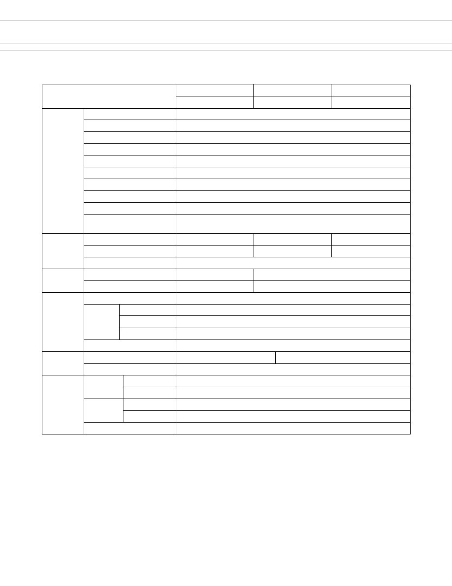
SPECIFICATIONS
Standard Type
Single Winding Latching Type Double Winding Latching Type
Item
A-( ) W-K
AL-( ) W-K
AL-D ( ) W-K
Contact
Arrangement
2 form C (DPDT)
Material
Gold overlay silver alloy
Resistance (initial)
Maximum 50 m
(at 1 A 6 VDC)
Rating (resistive)
0.5 A 125 VAC or 1 A 30 VDC
Maximum Carrying Current
2 A
Maximum Switching Power
62.5 AV/30 W
Maximum Switching Voltage
250 VAC, 220 VDC
Maximum Switching Current
2 A
Minimum Switching Load*
1
0.01 mA 10 mVDC
Capacitance
Approximately 0.5 pF (between open contacts, adjacent contacts)
Approximately 1.0 pF (between coil and contacts)
Coil
Nominal Power (at 20
∞
C)
0.14 to 0.3 W 0.1 to 0.15 W
0.20 to 0.3 W
Operate Power (at 20
∞
C)
0.08 to 0.17 W 0.06 to 0.85 W 0.15 to 0.17 W
Operating Temperature
≠40
∞
C to +85
∞
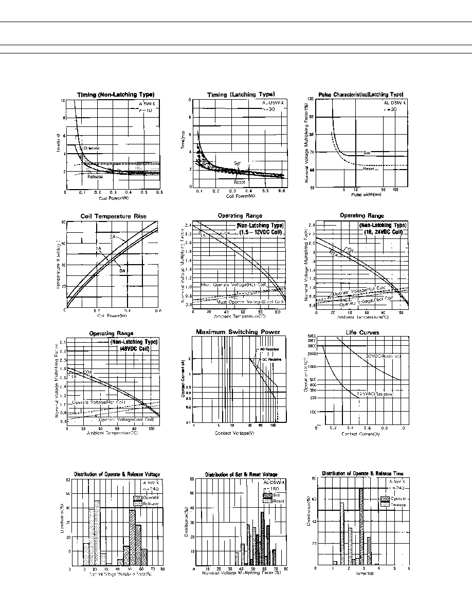
C (no frost) (refer to the CHARACTERISTIC DATA)
Time Value
Operate (at nominal voltage)
Maximum 6 ms Maximum 6 ms (set)
Release (at nominal voltage)
Maximum 4 ms Maximum 6 ms (reset)
Insulation
Resistance (at 500 VDC)
Minimum 1,000 M
between open contacts
1,000 VAC 1 minute
Dielectric
between adjacent contacts
1,000 VAC 1 minute
Strength
between coil and contacts
1,000 VAC 1 minute
Surge Strength
1,500 V (between coil and contacts)
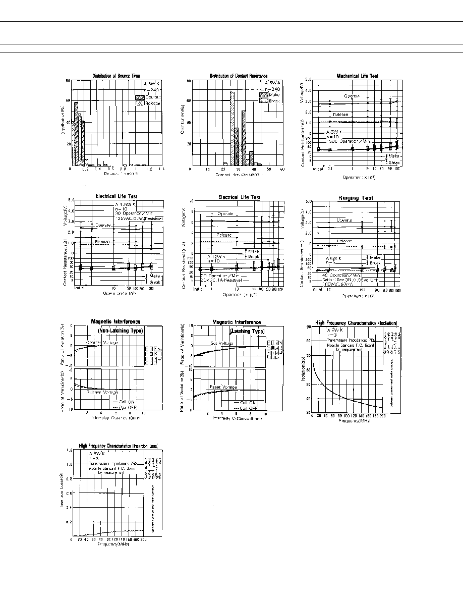
Life
Mechanical
1
◊
10
8
operations minimum 1
◊
10
7
operations minimum
Electrical
2
◊
10
5
ops. min. (0.5 A 125 VAC), 5
◊
10
5
ops. min. (1 A 30 VDC)
Other
Vibration Misoperation
10 to 55 Hz (double amplitude of 3.3 mm)
Resistance Endurance
10 to 55 Hz (double amplitude of 5.0 mm)
Shock Misoperation
500 m/s
2
(11
±
1 ms)
Resistance Endurance
1,000 m/s
2
( 6
±
1 ms)
Weight
Approximately 1.2 g
*
1
Minimum switching loads mentioned above are reference values. Please perform the confirmation test with the actual
load before production since reference values may vary according to switching frequencies, environmental conditions
and expected reliability levels.
3
A SERIES
Nominal
Coil resistance
Must operate
Must release
Nominal
MODEL
voltage
(
±
10%)
voltage*
1
voltage*
1
power
A-1.5W-K
1.5 VDC
16.1
+1.05 VDC
+0.15 VDC
140 mW
A- 3 W-K
3 VDC
64.3
+2.1 VDC
+0.3 VDC
140 mW
A-4.5W-K
4.5 VDC
145
+3.15 VDC
+0.45 VDC
140 mW
A- 5 W-K
5 VDC
178
+3.5 VDC
+0.5 VDC
140 mW
A- 6 W-K
6 VDC
257
+4.2 VDC
+0.6 VDC
140 mW
A- 9 W-K
9 VDC
579
+6.3 VDC
+0.9 VDC
140 mW
A-12 W-K
12 VDC
1,028
+8.4 VDC
+1.2 VDC
140 mW
A-18 W-K
18 VDC
1,620
+12.6 VDC
+1.8 VDC
200 mW
A-24 W-K
24 VDC
2,880
+16.8 VDC
+2.4 VDC
200 mW
A-48 W-K
48 VDC
7,680
+33.6 VDC
+4.8 VDC
300 mW
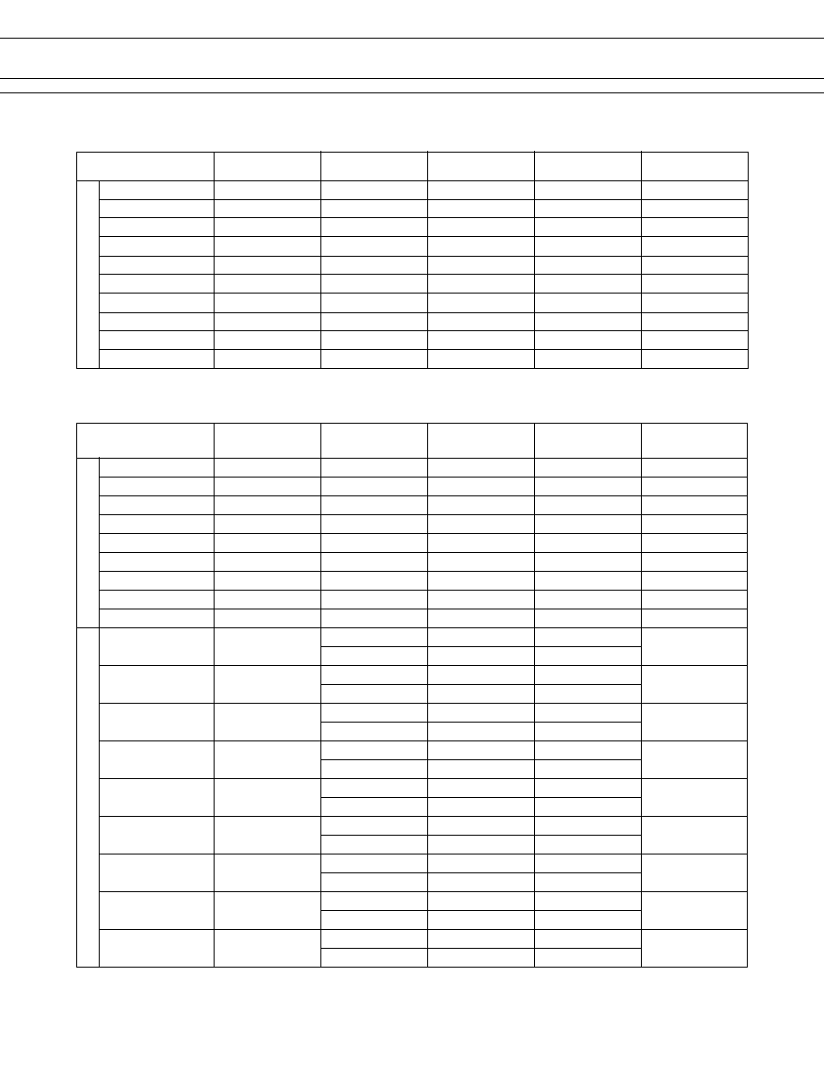
s
COIL DATA CHART
Standard T
ype
Nominal
Coil resistance
Set
Reset
Nominal
MODEL
voltage
(
±
10%)
voltage*
1
voltage*
1
power
AL-1.5W-K
1.5 VDC
22.5
+1.05 VDC
-1.05 VDC
100 mW
AL- 3 W-K
3 VDC
90
+2.1 VDC
-2.1 VDC
100 mW
AL-4.5W-K
4.5 VDC
203
+3.15 VDC
-3.15 VDC
100 mW
AL- 5 W-K
5 VDC
250
+3.5 VDC
-3.5 VDC
100 mW
AL- 6 W-K
6 VDC
360
+4.2 VDC
-4.2 VDC
100 mW
AL- 9 W-K
9 VDC
810
+6.3 VDC
-6.3 VDC
100 mW
AL-12 W-K
12 VDC
1,440
+8.4 VDC
-8.4 VDC
100 mW
AL-18 W-K
18 VDC
2,160
+12.6 VDC
-12.6 VDC
150 mW
AL-24 W-K
24 VDC
3,840
+16.8 VDC
-16.8 VDC
150 mW
AL-D1.5W-K
1.5 VDC
P 11.25
+1.05 VDC
200 mW
S 11.25
+1.05 VDC
AL-D 3 W-K
3 VDC
P 45
+2.1 VDC
200 mW
S 45
+2.1 VDC
AL-D4.5W-K
4.5 VDC
P 101
+3.15 VDC
200 mW
S 101
+3.15 VDC
AL-D 5 W-K
5 VDC
P 125
+3.5 VDC
200 mW
S 125
+3.5 VDC
AL-D 6 W-K
6 VDC
P 180
+4.2 VDC
200 mW
S 180
+4.2 VDC
AL-D 9 W-K
9 VDC
P 405
+6.3 VDC
200 mW
S 405
+6.3 VDC
AL-D12 W-K
12 VDC
P 720
+8.4 VDC
200 mW
S 720
+8.4 VDC
AL-D18 W-K
18 VDC
P 1,080
+12.6 VDC
300 mW
S 1,080
+12.6 VDC
AL-D24 W-K
24 VDC
P 1,920
+16.8 VDC
300 mW
S 1,920
+16.8 VDC
Single W
inding Latching
T
ype
Double Winding Latching
T
ype
P: Primary coil S: Secondary coil
Note: *
1
Specified values are subject to pulse wave voltage.
All values in the table are measured at 20
∞
C.
Note: *
1
Specified values are subject to pulse wave voltage.
All values in the table are measured at 20
∞
C.