DS04-23122-4E
FUJITSU MEDIA DEVICE
DATA SHEET
ASSP Mobile Communication Systems
Piezoelectric SAW BPF
(700 to 1700MHz)
F5CP/F6CP Series (D2 type)
s
s
s
s
DESCRIPTION
The F5CP/F6CP series of SAW band pass filters have 2.5 mm
◊
2.0 mm
◊
0.9 mm (h) of ultra small package,
which are available in the 700 to 2000 MHz frequency range. They exhibit high stability by using single crystal,
Lithium Tantalate (LiTaO
3
) with a large electro-mechanical coefficient.
Typical applications for the F5CP/F6CP series include RF interstage filtering in mobile communications systems.
Standard devices are available for AMPS, GSM, EGSM, PDC800, PDC1.5G.
s
s
s
s
FEATURES
∑ Ultra compact and light package (2.5 mm
◊
2.0 mm
◊
0.9 mm (h) *)
*: 1.0 mm height maximum
∑ Excellent stop band attenuation
∑ External matching are not required (50
I/O)
∑ Standard devices are available for mobile communication standards
s
s
s
s
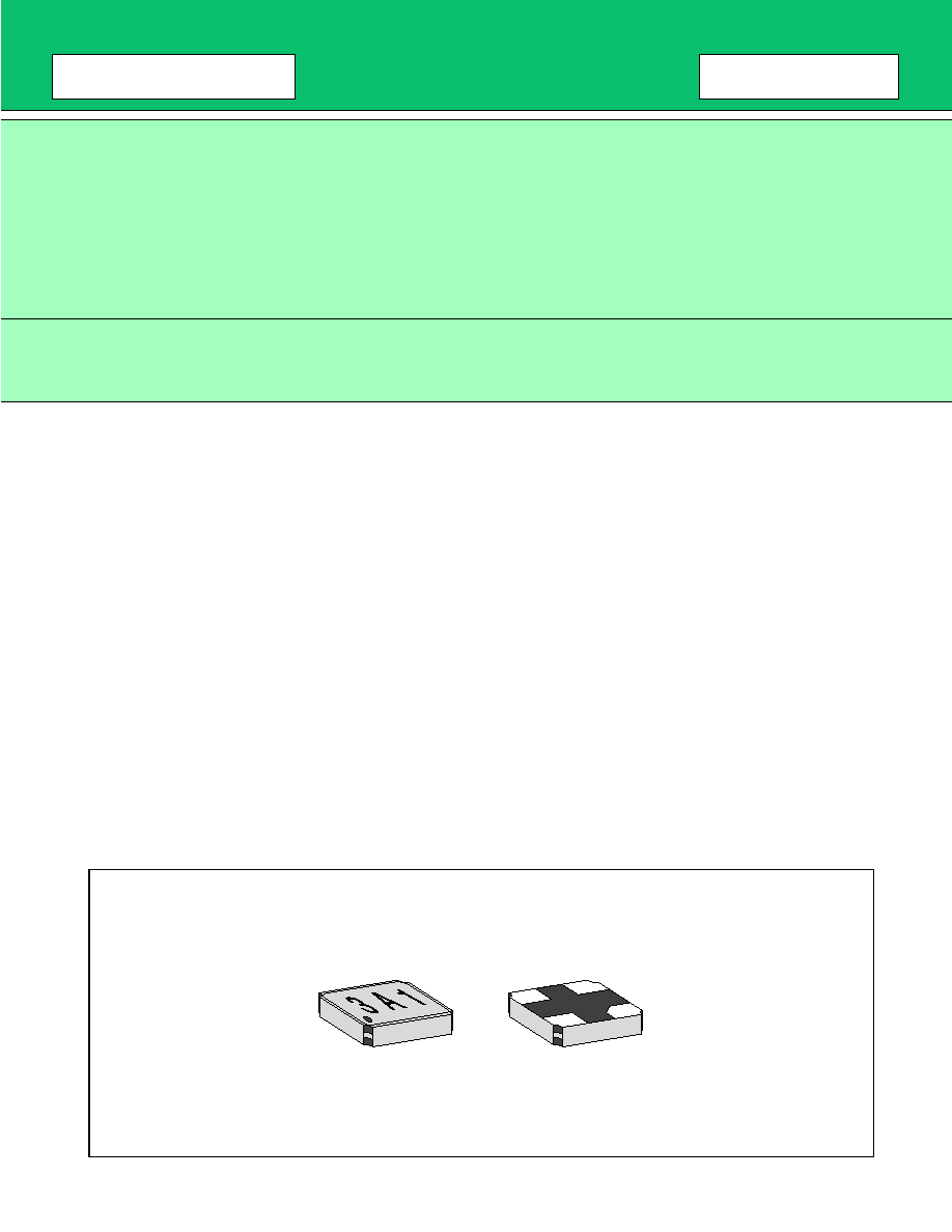
PACKAGE
F5CP/F6CP Series
3
s
s
s
s
ABSOLUTE MAXIMUM RATINGS
WARNING: Piezoelectric devices can be permanently damaged by application of stress (voltage, current,
temperature, etc.) in excess of absolute maximum ratings. Do not exceed these ratings.
s
s
s
s
RECOMMENDED OPERATING CONDITIONS
WARNING: The recommended operating conditions are required in order to ensure the normal operation of the
piezoelectric device. All of the device's electrical characteristics are warranted when the device is
operated within these ranges.
Always use piezoelectric devices within their recommended operating conditionranges. Operation
outside these ranges may adversely affect reliability and could result in device failure.
No warranty is made with respect to uses, operating conditions, or combinations not represented on
the data sheet. Users considering application outside the listed conditions are advised to contact their
FUJITSU representatives beforehand.
s
s
s
s
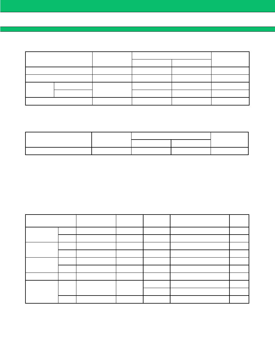
STANDARD DEVICES
Parameter
Symbol
Rating
Unit
Min.
Max.
Ambient operating temperature
Ta
-
30
+
85
∞
C
Storage temperature
Tstg
-
40
+
100
∞
C
Input power
F5CP Series
Pin
+
15
dBm
F6CP Series
+
10
dBm
Input DC voltage
-
5
+
5
V
Parameter
Symbol
Value
Unit
Min.
Max.
Operating temperature
Ta
-
30
+
85
∞
C
System
Center
frequency (MHz)
Band width
(MHz)
Part
symbol
Part number
Re-
marks
PDC800
T
X
950.0
20
9
FAR-F5CP-950M00-D209
R
X
820.0
20
2
FAR-F5CP-820M00-D202
AMPS/CDMA/
TDMA
T
X
836.5
25
3
FAR-F5CP-836M50-D203
R
X
881.5
25
4
FAR-F5CP-881M50-D204
GSM
T
X
902.5
25
5
FAR-F5CP-902M50-D205
R
X
947.5
25
6
FAR-F5CP-947M50-D206
EGSM
R
X
942.5
35
1
FAR-F5CP-942M50-D201
PDC1.5G
T
X
1441.0
24
7
FAR-F6CP-1G4410-D207
R
FAR-F6CP-1G4410-D20R
R
X
1489.0
24
8
FAR-F6CP-1G4890-D208
F5CP/F6CP Series
4
s
s
s
s
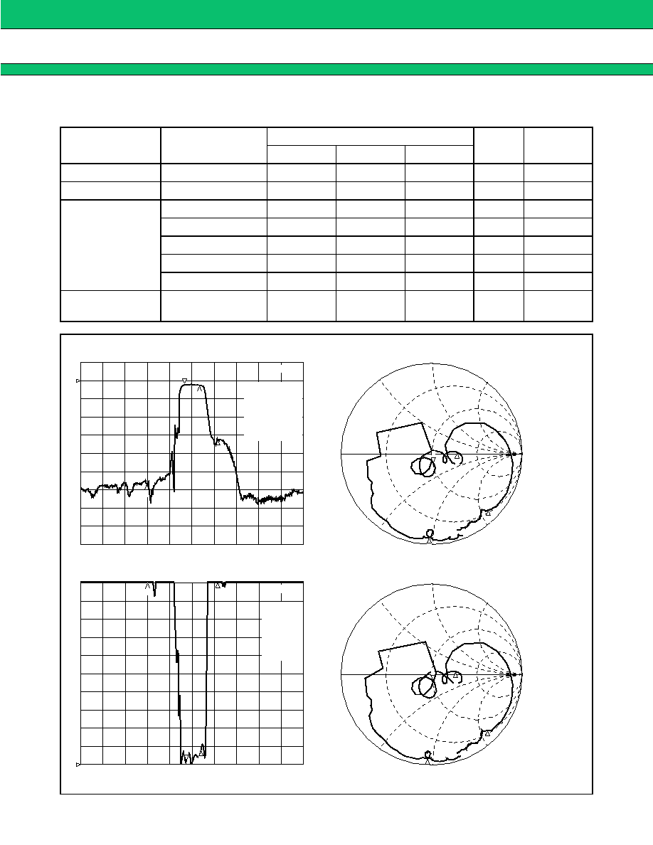
ELECTRICAL CHARACTERISTICS AND TYPICAL FREQUENCY RESPONSE
1.
SYSTEM : PDC800-Tx
PART NUMBER : FAR-F5CP-950M00-D209
Parameter
Conditions
Value
Unit
Remarks
Min.
Typ.
Max.
Insertion loss
940 to 960 MHz
3.1
3.5
dB
In-band ripple
940 to 960 MHz
0.8
1.2
dB
Absolute
attenuation
DC to 830 MHz
45
52
dB
1015 to 1106 MHz
35
42
dB
1106 to 1700 MHz
45
55
dB
1700 to 2000 MHz
40
48
dB
In-band VSWR
(Return loss)
940 to 960 MHz
(8.1)
2.1
(9.0)
2.3
(
)
(dB)
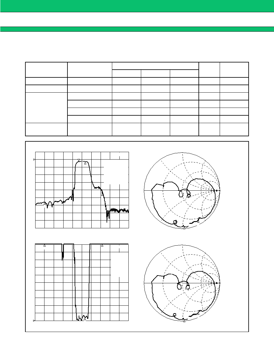
2
1
S
11
1U FS
1 : 51.404
-
11.736
S
21
log MAG
10 dB/ REF 0 dB
CENTER 950 MHz
SPAN 300 MHz
CENTER 950 MHz
SPAN 300 MHz
1 :
-
2.8224 dB
940 MHz
S
22
1U FS
1 : 48.162
-
11.197
S
11
SWR
1 / REF 1
CENTER 950 MHz
SPAN 300 MHz
CENTER 950 MHz
SPAN 300 MHz
1 : 1.2627
940 MHz
3
4
3
3
4
4
2
1
3
4
1
1
2
14.426 pF
940 MHz
2 : 65.227
-
15.25
960 MHz
3 : 3.3965
-
52.201
830 MHz
4 : 13.656
-
85.102
1.015 GHz
2 :
-
2.672 dB
960 MHz
3 :
-
55.793 dB
830 MHz
4 :
-
43.18 dB
1.015 GHz
2 : 1.4555
960 MHz
3 : 30.774
830 MHz
4 : 14.488
1.015 GHz
15.121 pF
940 MHz
2 : 62.332
-
11.52
960 MHz
3 : 3.3203
-
51.557
830 MHz
4 : 14.066
-
83.52
1.015 GHz
2