DS07-10205-1E
FUJITSU SEMICONDUCTOR
DATA SHEET
Resonator
Piezoelectric Resonator
(4 to 20 MHz)
FAR Family (C3 series M/N type)
s
DESCRIPTION
The features of the C3 series (M,N Type) resonators are compact and high stability. They are fabricated on a
lithium tantalate (LitaO
3
) substrate, producing resonators with ultra compact and superior stability due to the
high electromechanical coupling coefficient of the material.
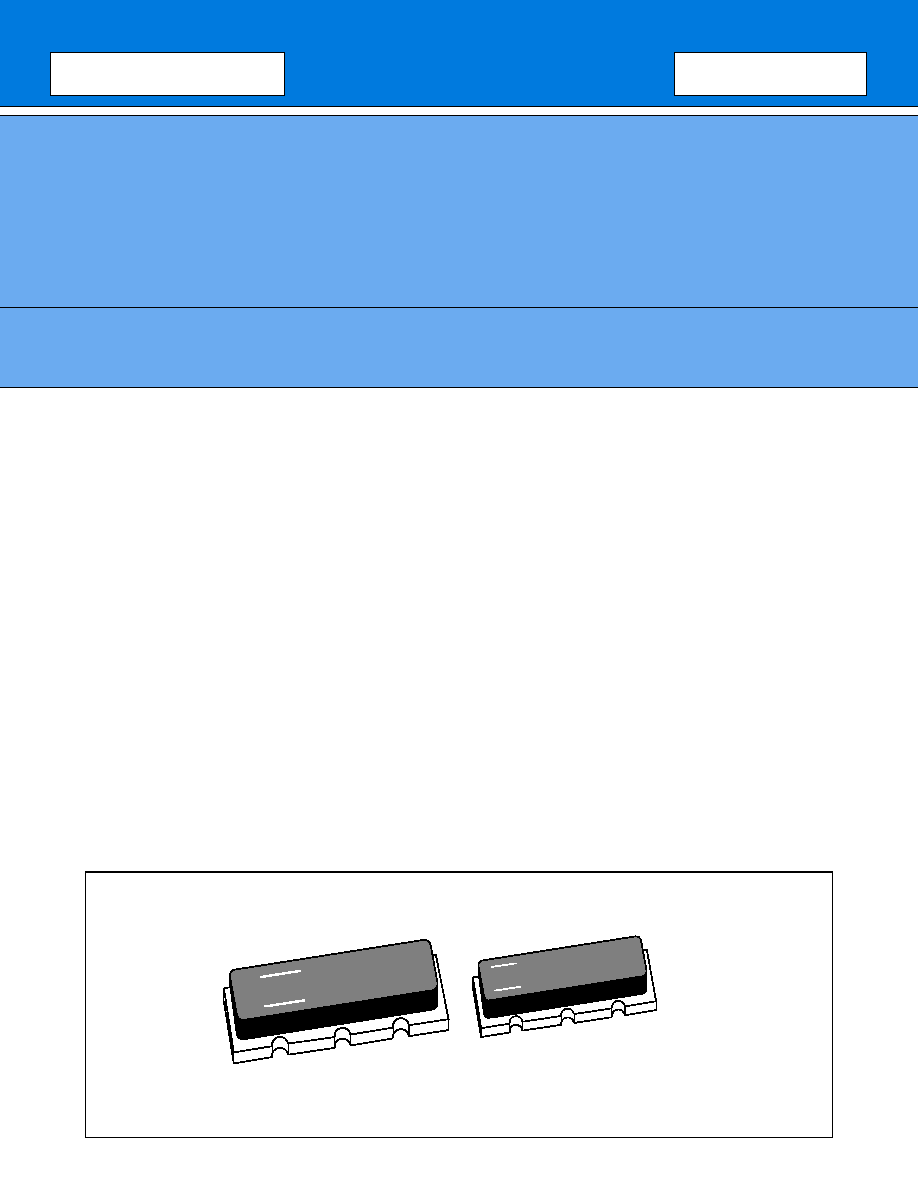
They include two loading capacitors inside and are housed in chip type of package for surface mount. These
contribute saving mount space and reducing cost.
s
FEATURES
∑ High stability (Overall frequency deviation; 0.10% max)
∑ Ultra small package
∑ Wide frequency range in 4 MHz to 20 MHz
∑ Suitable for microcomputer clock
∑ Emboss-typed pack for automatic mounting
∑ Superior shock and vibration resistance, preventing damage during automatic mounting
s
PACKAGE
F
4.00
FH
F
16.0FH
2
FAR Family (C3 series M/N type)
s
STANDARD CHARACTERISTICS
C3 series
Remarks
Material
Lithium Tantalate (LiTaO
3
)
Frequency
4 MHz to 20 MHz
Standard frequency
See "
s
Standard Frequency."
Initial frequency deviation
(F),
±
0.05% (G)
±
0.1% (J) and
±
0.3% (K) are also
available upon request.
Temperature characteristics
+0.035%
≠0.025%
(Within ≠10
∞
C to +60
∞
C)
Reference temperature: +25
∞
C
Capacity of built-in capacitor
20
±
8 pF (Standard)
10
±
4 pF are also available.
Capacity is specified by Fujitsu,
considering matching data with
applied IC (mainly microcomputer).
Operating temperature
≠30
∞
C to +85
∞
C
Storage temperature
≠40
∞
C to +100
∞
C
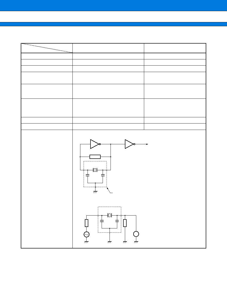
Standard measuring circuit
∑ Oscillation frequency
∑ Serial resonant resistance
+0.025%
≠0.035%
1 M
R
C
1
C
2
Microcomputer
1/6MC74ACO4
◊
2
(4 MHz to 8 MHz)
1/6TC74ACO4
◊
2
(8 MHz to 20 MHz)
∑
V
CC
= 5.0 V DC
∑
R: Resonator
∑
C
1
, C
2
: Loading capacitors (built-in)
FAR
C
1
C
2
LM
R
75
75
OSC
R: Resonator
Measuring equipment: Spectrum analyzer
Series
Item
3
FAR Family (C3 series M/N type)
s
STANDARD FREQUENCY
Notes: ∑ Fujitsu can also develop another frequency device besides standard devices within 4 MHz to 20 MHz.
∑ Regarding resonant resistance, maximum standard values are specified depending on frequency.
s
NOTES ON USE
∑ Handle carefully.
∑ Solder heat resistance.
5 seconds max. at +230
∞
C (on PCB)
Recommended preheating is +150
∞
C for one minute for avoiding giving extreme heat fluctuation to resonator.
∑ Avoid using resonator under condition of extreme temperature fluctuation.
∑ There is no specific direction in resonator mounting.
∑ Oscillation data must be considered in case that this resonator is used as microcomputer clock.
∑ Resonator is designed for reflow solder, not for flow solder.
Standard frequency (kHz)
Package size
Resonant resistance
4,000
4,194
M
300
max.
(Symbol: 0)
6,000
8,000
10,000
12,000
16,000
16,934
20,000
N
150
max.
(Symbol: 1)
4
FAR Family (C3 series M/N type)
s
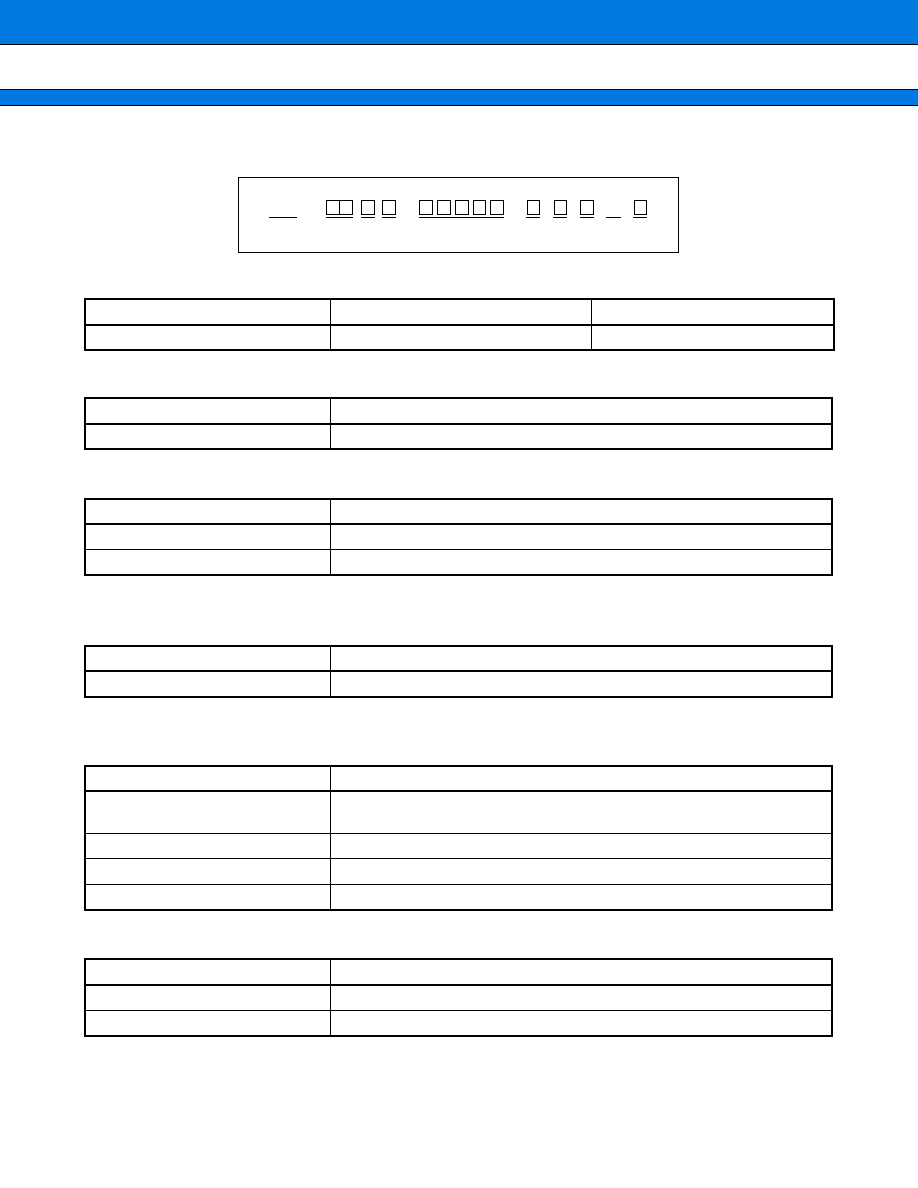
PART NUMBERING SYSTEM
(1) Series
(2) Package type
(3) Package size
(4) Oscillation frequency
Frequency is specified with 5-digit in kHz of unit.
See "
s
Standard Frequency."
(5) Initial frequency deviation
(6) Built-in capacitors
Series
Material
Capacitators
C3
LiTaO
3
Built-in type
Symbol
Type
C
Chip
Symbol
Size
M
4.5
◊
10.0
◊
2.0 mm (4.0 MHz to 5.9 MHz)
N
3.2
◊
8.0
◊
1.6 mm (6.0 MHz to 20.0 MHz)
Frequency
Symbol
[Example] 8.000 MHz
08000
Symbol
Deviation
F
+0.025%
≠0.035%
G
±
0.05%
J
±
0.1%
K
±
0.3%
Symbol
Capacitor
0
20
±
8 pF
1
10
±
4 pF
FAR
C
(1) (2)
--
--
--
--
C
3
(3)
(4)
(5) (6) (7) (8) (9)
5
FAR Family (C3 series M/N type)
(7) Resonant resistance
(8) Special mark
(9) Taping specification
Symbol
Resistance
0
300
max.
1
150
max.
Symbol
Content
Space
Standard device, no taping specification
--
Standard device, with Tape & Reel
H to Z
Serial number for custom design
Symbol
Content
R
16 mm width emboss tape (3,000 pcs/reel)