DS07-10203-1E
FUJITSU SEMICONDUCTOR
DATA SHEET
Resonator
Piezoelectric Resonator
(4 to 23.9 MHz)
FAR Family (C4 series N type)
s
DESCRIPTION
Fujitsu resonators C4 series (N type) feature originally developed single crystals with a high electro-mechanical
coefficient (LiNbO
3
: lithium niobate), the result is very compact packaging.
C4 series (N type) with built-in capacitors for exclusive use in microcomputer clocks, and this series is ultra low
profile CHIP type device for surface-mount (SMT).
s
FEATURES
∑ Ultra low profile H = 1.6 mm
∑ Direct oscillation in 4 to 23.9 MHz frequency.
∑ Suitable for the source of microcomputer clock
∑ Emboss-typed pack for automatic mounting
∑ Superior shock and vibration resistance, preventing damage during automatic mounting
s
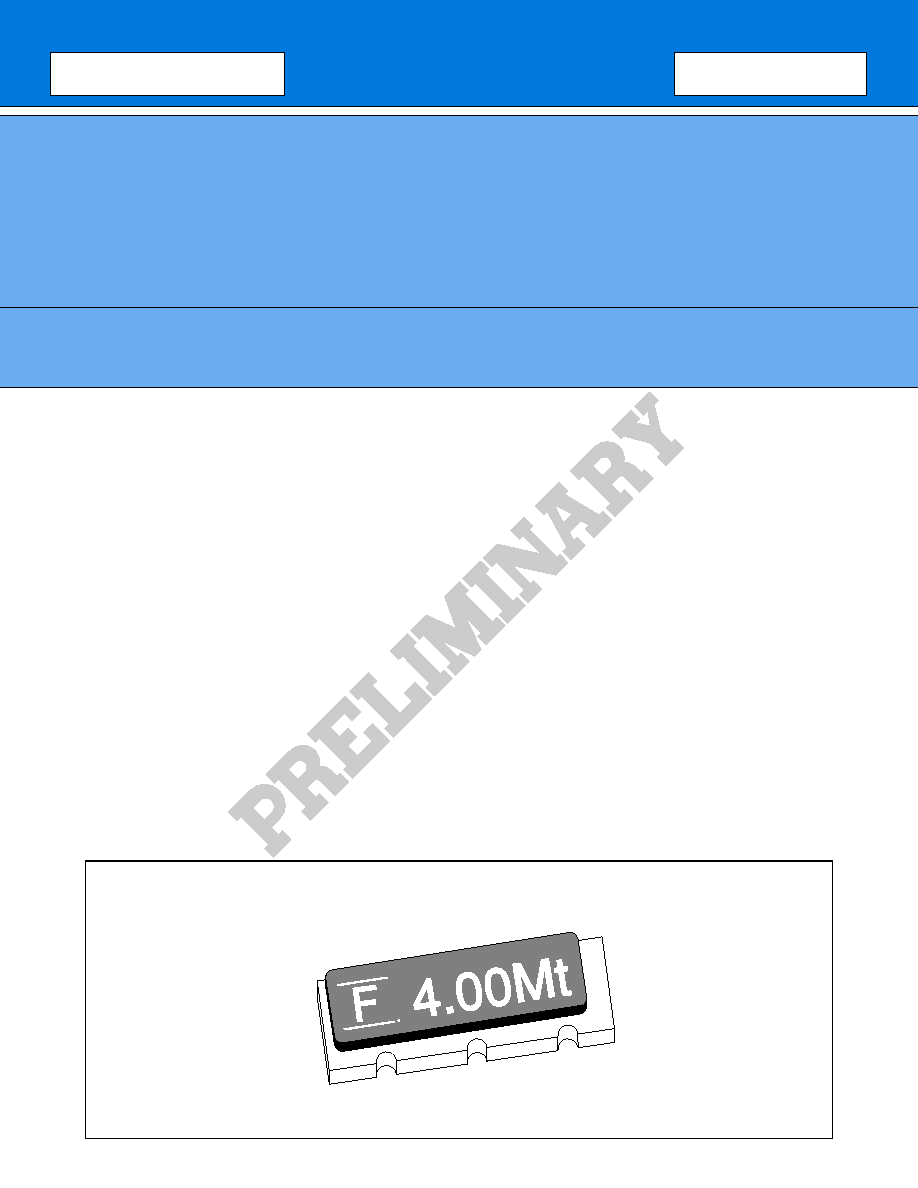
PACKAGE
2
FAR Family (C4 series N type)
s
STANDARD CHARACTERISTICS
C4 series (N type)
Remarks
Material
Lithium Niobate (LiNbO
3
)
Frequency
4 to 17 MHz
17.1 to 23.9 MHz
Standard frequency
See "
s
Standard Frequency."
Initial frequency deviation
±
0.3% (K)
±
0.5% (M)
±
1.0% (L)
±
1.0% (L)
When a frequency of more than
17.1 MHz, only L deviation type can
be made.
Temperature characteristic
(≠20
∞
C to +60
∞
C)
±
0.5%
Capacity of built-in capacitor
20
±
8 pF (standard)
10
±
4 pF, 30
±
8 pF are also available.
Capacity is specified by Fujitsu,
considering matching data with
applied IC (mainly microcomputer).
Aging stability
Within
±
0.1%
Operating temperature
≠30
∞
C to +85
∞
C
Storage temperature
≠40
∞
C to +100
∞
C
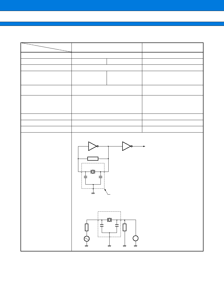
Standard measuring circuit
∑ Resonant frequency
∑ Serial resonant resistance
1 M
R
C
1
C
2
Less than 4 MHz to 10 MHz
IC: 1/6MB84069B
◊
2
10 MHz to 20.0 MHz
IC: 1/6MC74HC04
◊
2
20.1 MHz to 23.9 MHz
IC: 1/6MC74HCU04
◊
2
∑ V
CC
: 5 V DC
∑ R: Resonator
∑ C
1
, C
2
: Loading capacitors (built-in)
FAR
C
1
C
2
LM
R
75
75
OSC
R: Resonator
Measuring instrument: Network analyzer
Series
Parameter
3
FAR Family (C4 series N type)
s
STANDARD FREQUENCY
Notes: ∑ Fujitsu can also develop applicable device in addition to standard devices if it's oscillation frequency is
from 4 to 23.9 MHz.
∑ Resonant resistance of the part other than standard, Fujitsu should specify its resonant resistance
according to applied frequency. (See "∑ Frequency and standard resonant resistance.")
∑ Frequency and standard resonant resistance
Note: Resonant resistance of custom designed part should be specified considering matching condition with
applicable IC by Fujitsu.
s
NOTES ON USE
∑ Handle carefully
∑ Solder under the following conditions.
5 seconds max. at 230
∞
C (PCB)
Recommended preheating is 150
∞
C for one minute in order not to apply extreme heat to the resonator.
∑ Avoid extreme fluctuations in temperature.
∑ There is no specific direction in resonator mounting.
∑ Oscillation data should be examined when used in oscillation circuit with micon or other ICs.
∑ This is for reflow solder, not for flow solder.
Standard frequency (kHz)
Package size
Resonant resistance
4,000
4,194
4,915
N
300
max.
(Symbol: 0)
6,000
6,144
7,373
8,000
8,388
9,830
10,000
11,059
12,000
12,288
14,746
16,000
16,934
19,661
20,000
N
75
max.
(Symbol: 2)
Frequency
Standard resonant resistance
4.00 to 5.99 MHz
300
max. (Symbol: 0)
6.00 to 23.99 MHz
75
max. (Symbol: 2)
4
FAR Family (C4 series N type)
s
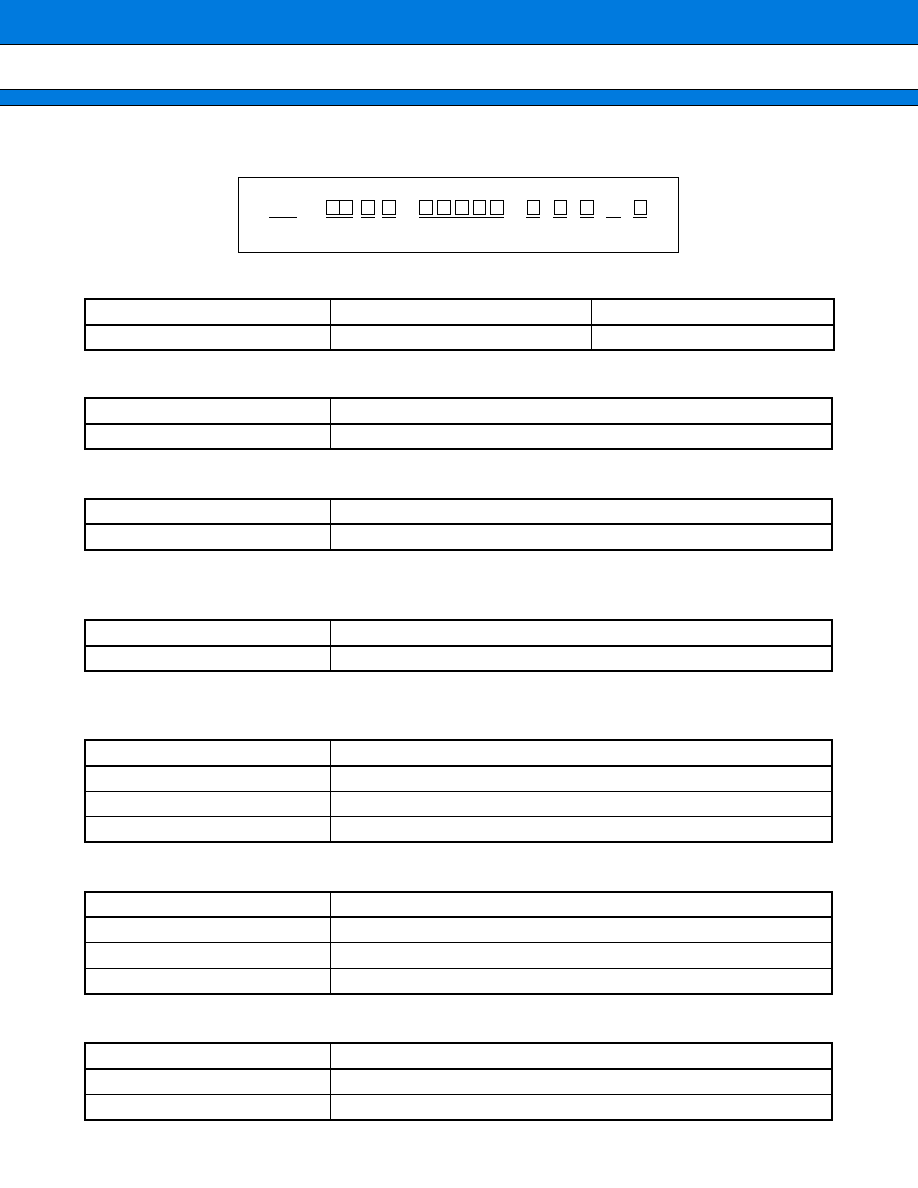
PART NUMBERING SYSTEM
(1) Series
(2) Package Type
(3) Package Type
(4) Frequency
(Example) Unit: kHz (Specify in five digits.)
See "
s
Standard Frequency".
(5) Initial Frequency Deviation
(6) Built-in Capacitor
(7) Resonant Resistance
Series
Single crystal
Capacitator
C4
LiNbO
3
With built-in capacitator
Specification
Type
C
CHIP
Specification
Size
N
8.0
◊
3.2
◊
1.6
Frequency
Specification
7.373 MHz
07373
Specification
Deviation
K
±
0.3%
M
±
0.5%
L
±
1.0%
Specification
Capacitance
0
20
±
8 pF
1
10
±
4 pF
2
30
±
8 pF
Specification
Resonant resistance
0
300
max.
2
75
max.
FAR
C
(1) (2)
--
--
--
--
C
4
(3)
(4)
N
(5) (6) (7) (8) (9)
5
FAR Family (C4 series N type)
(8) User-specific Special Symbols
(9) Resonant Resistance
Specification
Description
Name
No specifications, no taping specification
--
No specifications, with taping specification
A to Z
Serial number for custom design
Specification
Description
R
16 mm wide emboss tape coiled 3,000 times
6
FAR Family (C4 series N type)
s
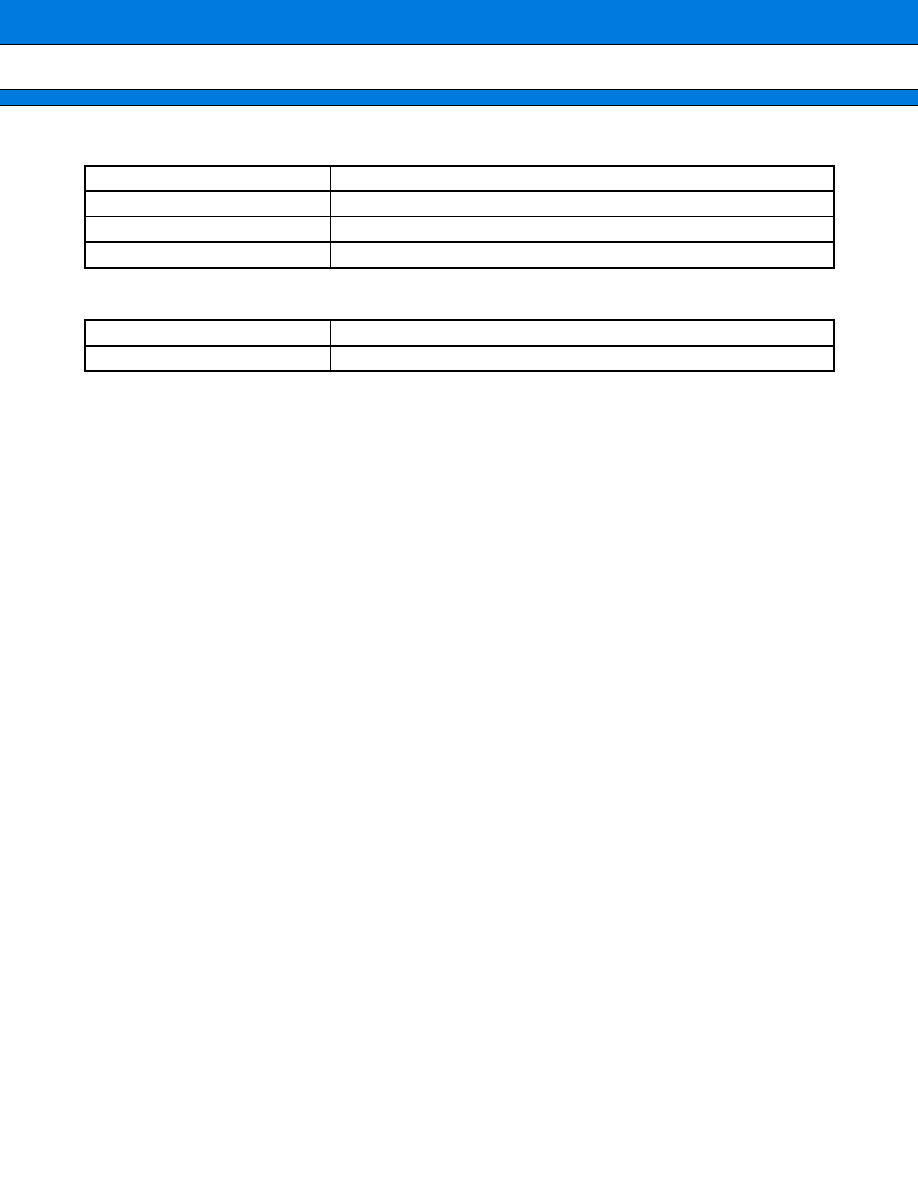
MARKING
s
PIN ASSIGNMENT
12.0 MV
F
Fujitsu logo
10 pF
20 pF
Capacitance
Yellow
White
30 pF
Gray
Marking color
Note: The marking color varies with the capacitance of the built-in capacitator.
Lot No. (Date of manufacture, conforms to EIAJ)
Frequency (MHz)
Initial frequency deviation
(1)
(3)
(3)
(2)
(2)
(1)
7
FAR Family (C4 series N type)
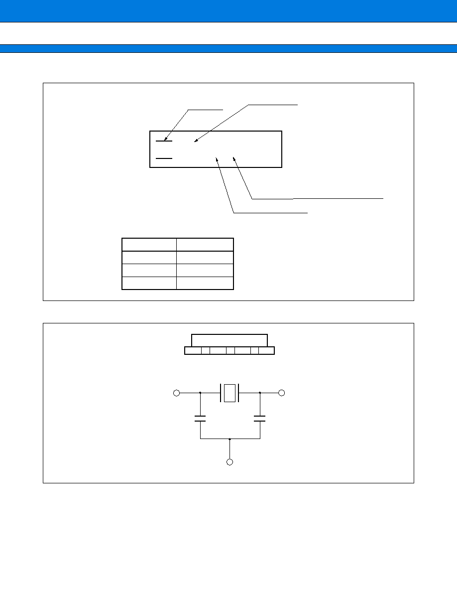
s
DIMENSIONS
Unit: mm
2.54
2.54
1.5
3.2
1.6
7.2
8.0
8
FAR Family (C4 series N type)
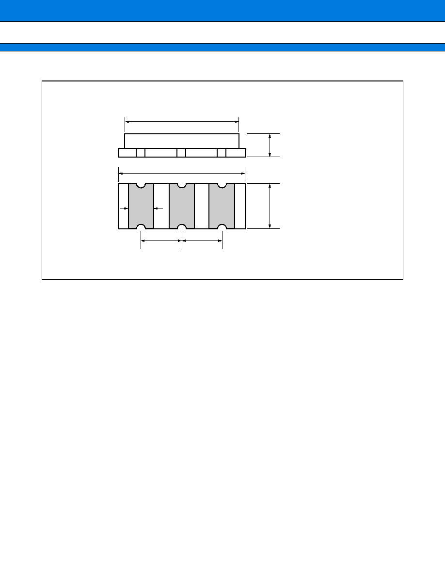
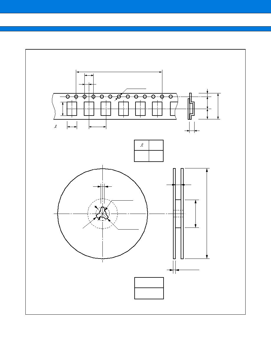
s
TAPING FORM AND DIMENSIONS
2.0
±
0.5
13.0
±
0.5
21.0
±
0.8
R1.0
80
2.0
±
0.5
330
±
0.2
18.0
±
1.5
8.0
±
0.1
W
±
0.1
±
0.1
16.0
±
0.2
7.65
±
0.2
1.5
±
0.1
1.5
±
0.1
0
4.0
±
0.1
2.0
±
0.1
Quantity
3,000
Pack quantity
Unit: mm
2.1
±
0.1
4.0
◊
10 = 40
±
0.2
(6.85)
W
3.7 8.5
Reel form

9
FAR Family (C4 series N type)
FUJITSU LIMITED
For further information please contact:
Japan
FUJITSU LIMITED
Corporate Global Business Support Division
Electronic Devices
KAWASAKI PLANT, 4-1-1, Kamikodanaka
Nakahara-ku, Kawasaki-shi
Kanagawa 211-88, Japan
Tel: (044) 754-3753
Fax: (044) 754-3332
North and South America
FUJITSU MICROELECTRONICS, INC.
Semiconductor Division
3545 North First Street
San Jose, CA 95134-1804, U.S.A.
Tel: (408) 922-9000
Fax: (408) 432-9044/9045
Europe
FUJITSU MIKROELEKTRONIK GmbH
Am Siebenstein 6-10
63303 Dreieich-Buchschlag
Germany
Tel: (06103) 690-0
Fax: (06103) 690-122
Asia Pacific
FUJITSU MICROELECTRONICS ASIA PTE. LIMITED
#05-08, 151 Lorong Chuan
New Tech Park
Singapore 556741
Tel: (65) 281-0770
Fax: (65) 281-0220
F9611
©
FUJITSU LIMITED Printed in Japan
All Rights Reserved.
Circuit diagrams utilizing Fujitsu products are included as a
means of illustrating typical semiconductor applications. Com-
plete information sufficient for construction purposes is not nec-
essarily given.
The information contained in this document has been carefully
checked and is believed to be reliable. However, Fujitsu as-
sumes no responsibility for inaccuracies.
The information contained in this document does not convey any
license under the copyrights, patent rights or trademarks claimed
and owned by Fujitsu.
Fujitsu reserves the right to change products or specifications
without notice.
No part of this publication may be copied or reproduced in any
form or by any means, or transferred to any third party without
prior written consent of Fujitsu.
The information contained in this document are not intended for
use with equipments which require extremely high reliability
such as aerospace equipments, undersea repeaters, nuclear con-
trol systems or medical equipments for life support.