1
DS04-23112-1E
FUJITSU SEMICONDUCTOR
DATA SHEET
ASSP
Mobile Communication Systems
Piezoelectric SAW BPF
(700 to 1000 MHz)
F5CH Series (L2 type)
s
DESCRIPTION
The F5CH series of SAW bandpass filters apply to the frequency range 700 to 1000 MHz.
The SAW filters are fabricated on a lithium tantalate (LiTaO
3
) substrate, producing filters with a wide frequency
bandwidth, low insertion loss in passband and superior stability due to the high electromechanical coupling coefficient
of the material.
The F5CH series filters are housed in a small surface mount package. Moreover, the impedance in the passband is
50 ohms, and so applications require no external matching circuits.
The F5CH series SAW filters are suitable for interstage RF filter in mobile communications systems in the frequency
range 700 to 1000 MHz. Standard devices are available for AMPS, ETACS, GSM, EGSM, PDC and so on.
s
FEATURES
� Low insertion loss and high attenuation
� High handling power (0.2 Watt)
� Ultra compact and light package (3.8 mm)
� External matching circuits are not required.
� Surface mount package (SMT)
� Wide variety of standard devices for worldwide mobile communication systems
(AMPS, GSM, EGSM, ETACS, PDC800, NTACS, 2 WAY PAGER etc.)
s
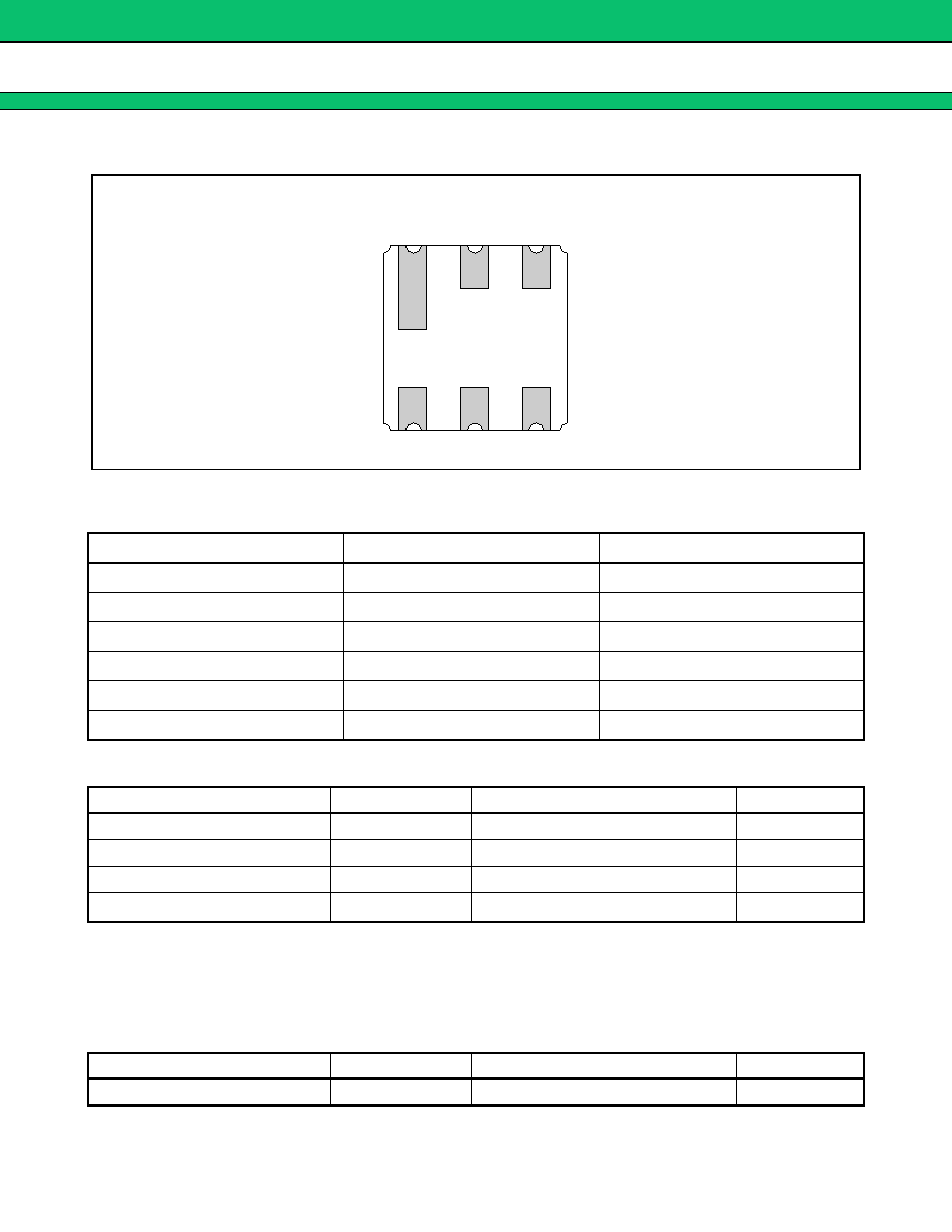
PACKAGE
MD
F
11
r
2
F5CH Series (L2 type)
s
PIN ASSIGNMENT
s
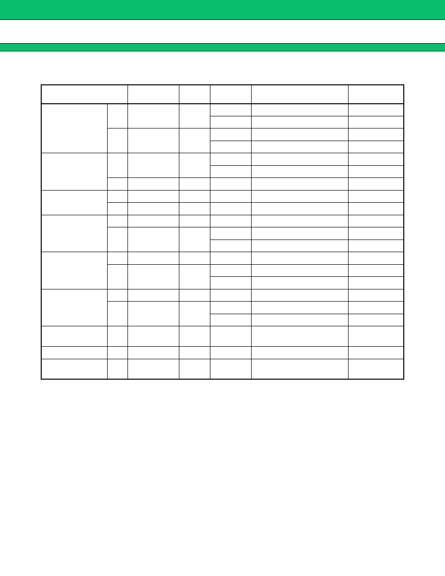
PIN DESCRIPTION
s
ABSOLUTE MAXIMUM RATINGS (See WARNING)
WARNING: Parmanent device damage may occur if the above Absolute Maximum Ratings are exceeded.
Functional operation should be restricted to the conditions as detailed in the operational sections of
this data sheet. Exposure to absolute maximum rating conditions for extended periods may affect
device reliability.
s
RECOMMENDED OPERATING CONDITIONS
Pin No.
Pin name
Description
1
GND
Ground Pin
2
IN
Input Pin
3
GND
Ground Pin
4
GND
Ground Pin
5
OUT
Output Pin
6
GND
Ground Pin
Parameter
Symbol
Rating
Unit
Operating temperature
T
a
�30 to +85
�
C
Storage temperature
T
stg
�40 to +100
�
C
Maximum input power
P
IN
200
mW
Frequency range
--
700 to +1000
MHz
Parameter
Symbol
Value
Unit
Operating temperature
T
a
�30 to +85
�
C
(Bottom View)
(1)
(2)
(3)
(6)
(5)
(4)
4
F5CH Series (L2 type)
s
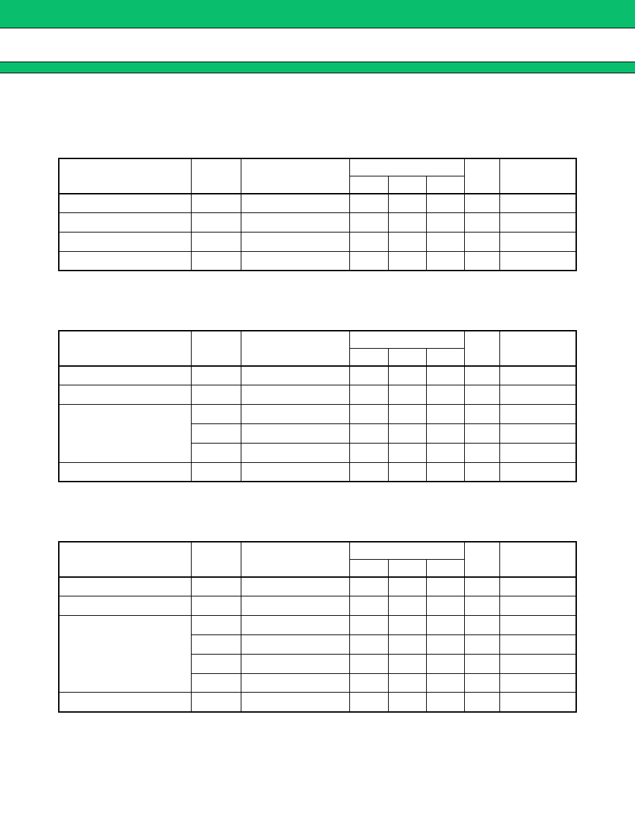
ELECTRIC CHARACTERISTICS
1.
AMPS/ADC (Tx)
Part number: FAR-F5CH-836M50-L2AL
(T
a
= �30 to +85
�
C)
2.
AMPS/ADC (Tx) High Attenuation Type
Part number: FAR-F5CH-836M50-L2AW
(T
a
= �30 to +85
�
C)
3.
AMPS/ADC (Rx)
Part number: FAR-F5CH-881M50-L2AM
(T
a
= �30 to +85
�
C)
Parameter
Symbol
Condition
Value
Unit
Remarks
Min.
Typ.
Max.
Insertion loss
IL
824 to 849 MHz
--
1.6
2.5
dB
Inband ripple
--
824 to 849 MHz
--
1.0
2.0
dB
Absolute attenuation
--
869 to 894 MHz
20
25
--
dB
Inband VSWR
--
824 to 849 MHz
--
1.8
2.0
--
Parameter
Symbol
Condition
Value
Unit
Remarks
Min.
Typ.
Max.
Insertion loss
IL
824 to 849 MHz
--
2.6
3.5
dB
Inband ripple
--
824 to 849 MHz
--
1.0
2.0
dB
Absolute attenuation
--
DC to 800 MHz
28
31
--
dB
--
869 to 1049 MHz
30
38
--
dB
--
1049 to 2000 MHz
25
30
--
dB
Inband VSWR
--
824 to 849 MHz
--
1.8
2.5
--
Parameter
Symbol
Condition
Value
Unit
Remarks
Min.
Typ.
Max.
Insertion loss
IL
869 to 894 MHz
--
2.5
3.5
dB
Inband ripple
--
869 to 894 MHz
--
1.0
2.0
dB
Absolute attenuation
--
DC to 849 MHz
20
24
--
dB
--
914 to 939 MHz
20
30
--
dB
--
939 to 1049 MHz
25
30
--
dB
--
1049 to 2000 MHz
20
23
--
dB
Inband VSWR
--
869 to 894 MHz
--
1.8
2.0
--
5
F5CH Series (L2 type)
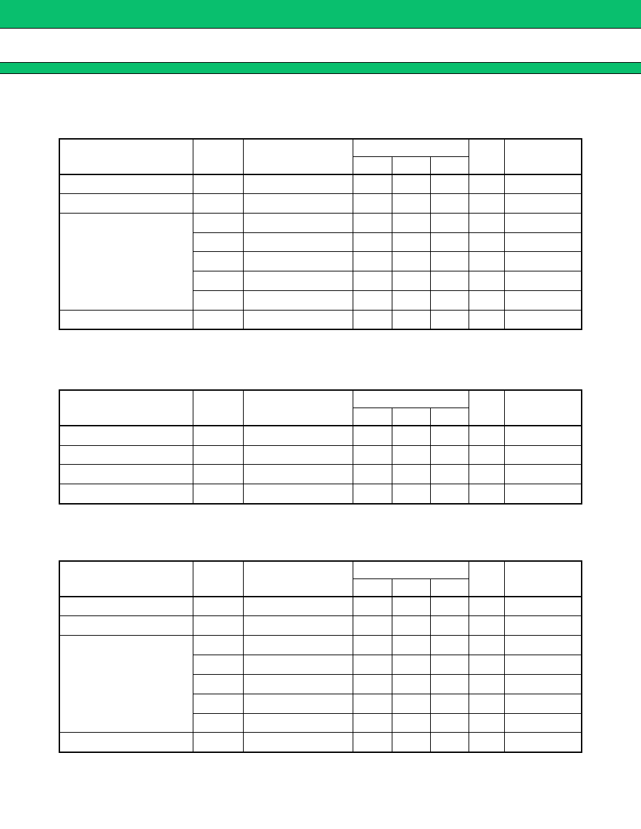
4.
AMPS/ADC (Rx) High Attenuation Type
Part number: FAR-F5CH-881M50-L2AV
(T
a
= �30 to +85
�
C)
5.
ETACS (Tx)
Part number: FAR-F5CH-888M50-L2CL
(T
a
= �30 to +85
�
C)
6.
ETACS (Tx) High Attenuation Type
Part number: FAR-F5CH-888M50-L2CW
(T
a
= �30 to +85
�
C)
Parameter
Symbol
Condition
Value
Unit
Remarks
Min.
Typ.
Max.
Insertion loss
IL
869 to 894 MHz
--
3.0
3.5
dB
Inband ripple
--
869 to 894 MHz
--
1.0
2.0
dB
Absolute attenuation
--
DC to 779 MHz
25
33
--
dB
--
779 to 849 MHz
35
40
--
dB
--
914 to 939 MHz
20
30
--
dB
--
939 to 1049 MHz
40
42
--
dB
--
1049 to 2000 MHz
25
30
--
dB
Inband VSWR
--
869 to 894 MHz
--
1.7
2.0
--
Parameter
Symbol
Condition
Value
Unit
Remarks
Min.
Typ.
Max.
Insertion loss
IL
872 to 905 MHz
--
3.0
5.0
dB
Inband ripple
--
872 to 905 MHz
--
1.5
--
dB
Absolute attenuation
--
917 to 950 MHz
10
15
--
dB
Inband VSWR
--
872 to 905 MHz
--
2.0
2.5
--
Parameter
Symbol
Condition
Value
Unit
Remarks
Min.
Typ.
Max.
Insertion loss
IL
872 to 905 MHz
--
3.8
5.5
dB
Inband ripple
--
872 to 905 MHz
--
2.0
--
dB
Absolute attenuation
--
DC to 850 MHz
30
34
--
dB
--
917 to 925 MHz
10
15
--
dB
--
925 to 950 MHz
20
30
--
dB
--
950 to 1100 MHz
35
45
--
dB
--
1100 to 2000 MHz
25
30
--
dB
Inband VSWR
--
872 to 905 MHz
--
2.0
3.5
--