
DS04-23110-5E
FUJITSU MEDIA DEVICE
DATA SHEET
ASSP
Mobile Communication Systems
Piezoelectric SAW BPF
(1000 to 2500 MHz)
F6 Series (L2 type)
s
s
s
s
DESCRIPTION
The F6 series of SAW band pass filters apply to the frequency range 1000 to 2500 MHz.
The SAW filters are fabricated on a lithium tantalate (LiTaO
3
) substrate, producing filters with a wide frequency
bandwidth, low insertion loss in passband and superior stability due to the high electromechanical coupling
coefficient of the material.
Fujitsu's leading techniques for making filter pattern designs realized this high frequency filter.
The F6 series filters are housed in a small surface mount package. Moreover, the impedance in the passband is
50
, and so applications require no external matching circuits.
The F6 series SAW filters are suitable for interstage RF filter in mobile communications systems in the sub
microwave frequency band. Standard devices are available for PCS, DCS1800, and 2.4 GHz wireless LAN
systems.
s
s
s
s
FEATURES
� High frequency filters
� Low insertion loss
� Ultra compact and light package (3.0 mm
�
3.0 mm)
� External matching circuits are not required.
� Surface mount package (SMT)
� Wide variety of standard devices for worldwide mobile communication systems
s
s
s
s
PACKAGE
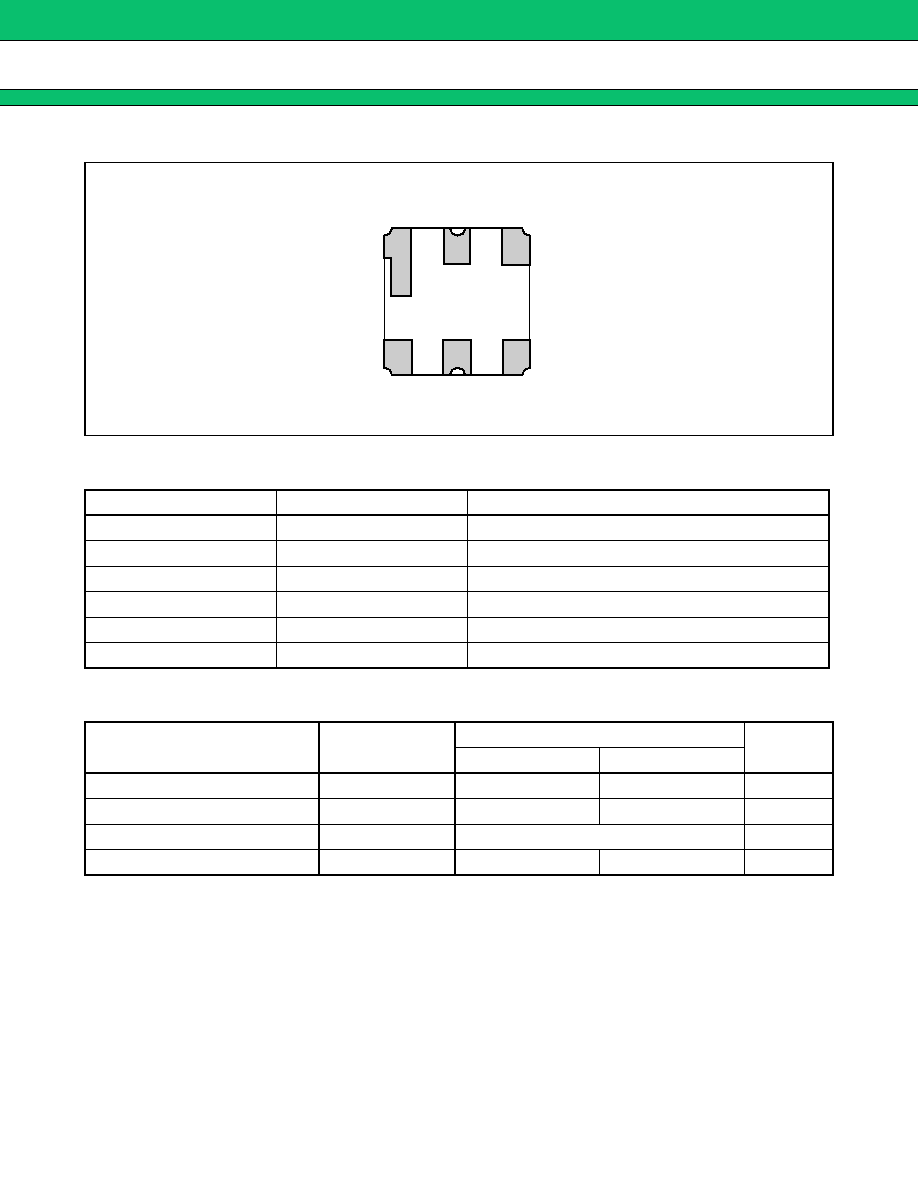
F6 Series (L2 type)
2
s
s
s
s
PIN ASSIGNMENT
s
s
s
s
PIN DESCRIPTION
s
s
s
s
ABSOLUTE MAXIMUM RATINGS
WARNING: Piezoelectric devices can be permanently damaged by application of stress (voltage, current,
temperature, etc.) in excess of absolute maximum ratings. Do not exceed these ratings.
Pin No.
Pin name
Description
1
GND
Ground
2
IN
Input
3
GND
Ground
4
GND
Ground
5
OUT
Output
6
GND
Ground
Parameter
Symbol
Value
Unit
Min.
Max.
Operating temperature
Ta
-
30
+
85
�
C
Storage temperature
Tstg
-
40
+
100
�
C
Maximum input level
P
IN
Refer to electrical characteristics
dBm
Input DC voltage
-
5
+5
V
(BOTTOM VIEW)
1
2
3
6
5
4
F6 Series (L2 type)
3
s
s
s
s
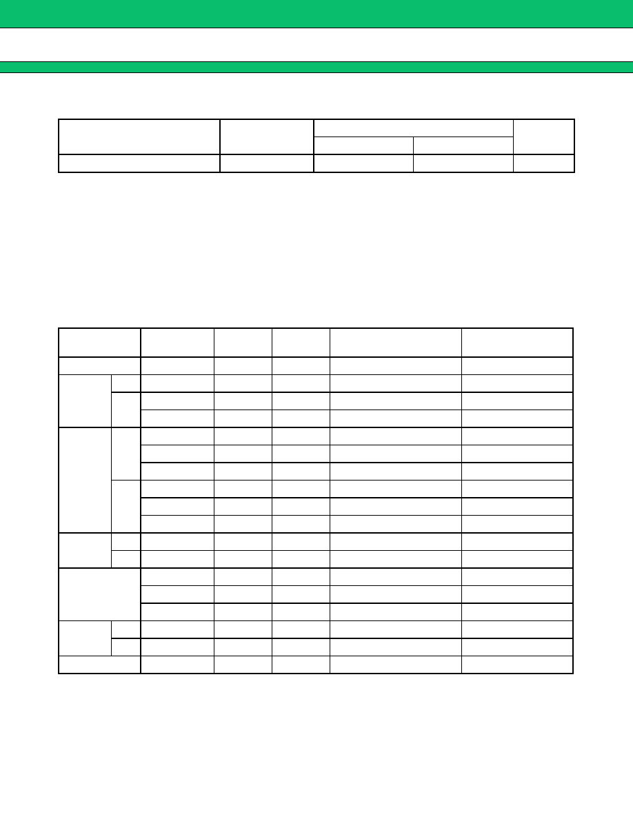
RECOMMENDED OPERATING CONDITIONS (See WARNING)
* : Standard Rating for Wireless LAN Systems is 0 to
+
60
�
C.
WARNING: The recommended operating conditions are required in order to ensure the normal operation of the
piezoelectric device. All of the device's electrical characteristics are warranted when the device is
operated within these ranges.
Always use piezoelectric devices within their recommended operating condition ranges. Operation
outside these ranges may adversely affect reliability and could result in device failure.
No warranty is made with respect to uses, operating conditions, or combinations not represented on
the data sheet. Users considering application outside the listed conditions are advised to contact their
FUJITSU representatives beforehand.
s
s
s
s
STANDARD FREQUENCIES
Parameter
Symbol
Value
Unit
Min.
Max.
Operating temperature *
Ta
-
30
+
85
�
C
System
Center freq.
(MHz)
Band
width
Part
symbol
Part number
Remarks
GPS
1575.42
2
6
FAR-F6CE-1G5754-L2UA
PCN
Tx
1747.5
75
A
FAR-F6CE-1G7475-L2YA
Rx
1842.5
75
B
FAR-F6CE-1G8425-L2YB
1842.5
75
YE
FAR-F6CE-1G8425-L2YE
Low insertion loss type
US-PCS
Tx
1880.0
60
C
FAR-F6CE-1G8800-L2XA
1880.0
60
c
FAR-F6CE-1G8800-L2XZ
High Att. type
1880.0
60
g
FAR-F6CE-1G8800-L2XJ
High Att. at Rx band
Rx
1960.0
60
D
FAR-F6CE-1G9600-L2XB
1960.0
60
d
FAR-F6CE-1G9600-L2XY
High Att. type
1960.0
60
v
FAR-F6CE-1G9600-L2XK
High Att. at Rx band
K-PCS
Tx
1765.0
30
S
FAR-F6CE-1G7650-L2TA
Rx
1855.0
30
T
FAR-F6CE-1G8550-L2TB
Wireless LAN
2448.5
97
E
FAR-F6CE-2G4500-L2WA
2484.0
26
P
FAR-F6CE-2G4840-L2WC For Japan
2441.8
83
L
FAR-F6CE-2G4418-L2WD For Europe, USA
W-CDMA
Tx
1950.0
60
j
FAR-F6CE-1G9500-L2ZP
Rx
2140.0
60
k
FAR-F6CE-2G1400-L2ZQ
Bluetooth
2441.8
83.5
RB
FAR-F6CE-2G4418-L2RB
F6 Series (L2 type)
4
s
s
s
s
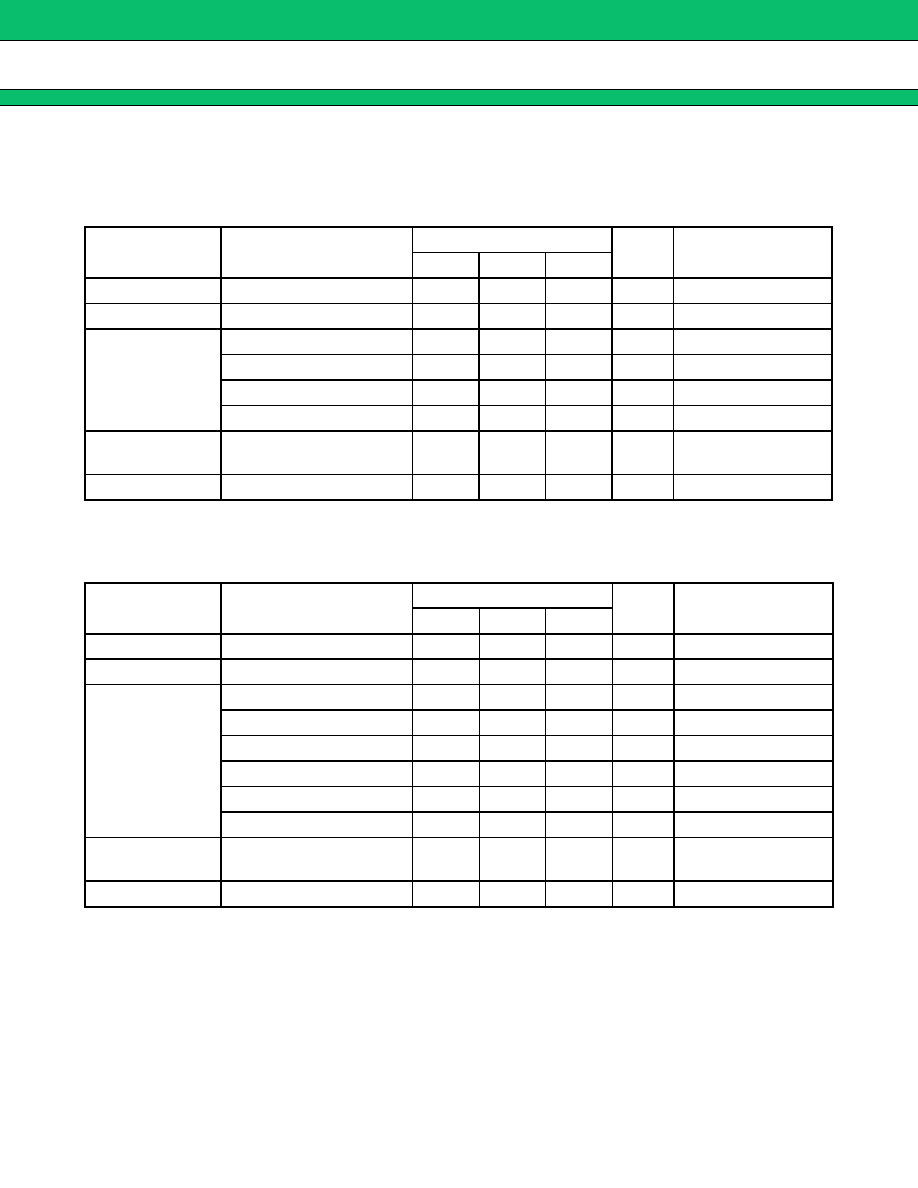
ELECTRICAL CHARACTERISTICS (STANDARD VERSION)
1.
GPS
Part number : FAR-F6CE-1G5754-L2UA
(Ta
=
-
30
�
C to
+
85
�
C)
2.
PCN (Tx)
Part number : FAR-F6CE-1G7475-L2YA
(Ta
=
-
30
�
C to
+
85
�
C)
Parameter
Conditions
Value
Unit
Remarks
Min.
Typ.
Max.
Insertion loss
1574.42 to 1576.42 MHz
2.7
3.5
dB
In-band deviation
1574.42 to 1576.42 MHz
0.2
1.0
dB
Absolute
stopband
attenuation
1475.42 MHz
35
37
dB
1525.42 MHz
35
50
dB
1625.42 MHz
30
38
dB
1675.42 MHz
30
35
dB
In-band VSWR
(Return loss)
1574.42 to 1576.42 MHz
(9.5)
1.4
(15.6)
2.0
(dB)
Max. input power
1574.42 to 1576.42 MHz
10
dBm
Parameter
Conditions
Value
Unit
Remarks
Min.
Typ.
Max.
Insertion loss
1710 to 1785 MHz
3.0
4.2
dB
In-band deviation
1710 to 1785 MHz
1.8
2.7
dB
Absolute
stopband
attenuation
DC to 1500 MHz
17
19
dB
1500 to 1670 MHz
20
22
dB
1805 to 1880 MHz
7
12
dB
1880 to 2200 MHz
20
23
dB
3420 to 3570 MHz
25
31
dB
5130 to 5355 MHz
15
25
dB
In-band VSWR
(Return loss)
1710 to 1785 MHz
(6.0)
2.5
(7.4)
3.0
(dB)
Max. input power
1710 to 1785 MHz
13
dBm

F6 Series (L2 type)
5
3.
PCN (Rx)
Part number : FAR-F6CE-1G8425-L2YB
(Ta
=
-
30
�
C to
+
85
�
C)
4.
PCN (Rx) Low insertion loss type
Part number : FAR-F6CE-1G8425-L2YE
(Ta
=
-
30
�
C to
+
85
�
C)
Parameter
Conditions
Value
Unit
Remarks
Min.
Typ.
Max.
Insertion loss
1805 to 1880 MHz
3.3
4.5
dB
In-band deviation
1805 to 1880 MHz
1.5
2.5
dB
Absolute
stopband
attenuation
DC to 1500 MHz
20
22
dB
1600 to 1710 MHz
22
24
dB
1710 to 1785 MHz
10
29
dB
1920 to 2400 MHz
25
27
dB
3610 to 3760 MHz
25
35
dB
5415 to 5640 MHz
15
21
dB
In-band VSWR
(Return loss)
1805 to 1880 MHz
(6.0)
2.5
(7.4)
3.0
(dB)
Max. input power
1805 to 1880 MHz
13
dBm
Parameter
Conditions
Value
Unit
Remarks
Min.
Typ.
Max.
Insertion loss
1805 to 1880 MHz
2.6
3.7
dB
In-band deviation
1805 to 1880 MHz
1.0
2.1
dB
Absolute
stopband
attenuation
DC to 1720 MHz
15
17
dB
1720 to 1765 MHz
25
28
dB
1765 to 1785 MHz
8
20
dB
1920 to 1980 MHz
15
23
dB
1980 to 2400 MHz
17
21
dB
2400 to 3500 MHz
20
23
dB
3500 to 4000 MHz
15
24
dB
4000 to 6000 MHz
5
8
dB
In-band VSWR
(Return loss)
1805 to 1880 MHz
(6.0)
2.6
(7.0)
3.0
(dB)
Max. input power
1805 to 1880 MHz
13
dBm