DS04-23121-3E
FUJITSU MEDIA DEVICE
DATA SHEET
ASSP
Mobile Communication Systems
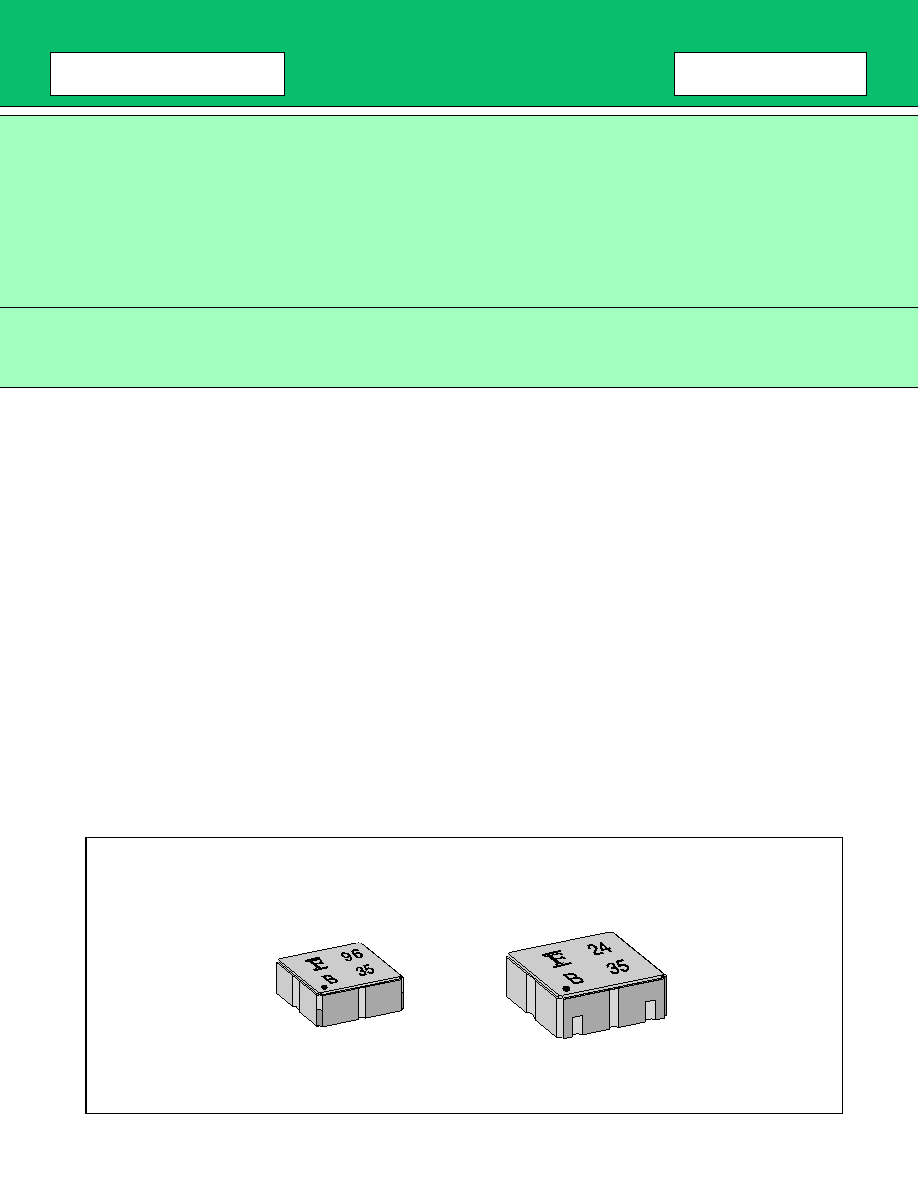
SAW Dual Filter
(700 to 2000 MHz)
G5/G6 Series (L2/D2 type)
s
s
s
s
DESCRIPTION
As the market for mobile phones continues to increase, so has demand for smaller size, lighter weight and lower
cost. Dual band phones, such as GSM
+
PCN and AMPS
+
PCS, are rising in popularity. To support these requests,
Fujitsu has developed a new series of SAW dual filter (G5/G6 series) incorporating two SAW filters in one package.
For example, Fujitsu can offer a GSM Rx filter and a PCN Rx filter of combination in small 3.8 mm
◊
3.8 mm.
package.
The G5/G6 series of SAW dual filter applies to the 700 to 2000 MHz, frequency range, and are available in two
package types : 2 input/2 output type or 1 input/2 output (2 input/1 output) .
s
s
s
s
FEATURES
∑ Two functions are incorporated in one package
(Useful for multi-band phone and multi-mode phone)
∑ Ultra compact and light package (3.8 mm
◊
3.8 mm. or 3.0 mm
◊
3.0 mm.)
∑ 50
of input/output impedance
∑ Low insertion loss
∑ 2 in/2 out and 1 in/2 out (2 in/1 out) of package types are available
s
s
s
s
PACKAGES
<
G5CN
>
<
G6CN
>
<
G6CH
>

G5/G6 Series
2
s
s
s
s
PIN ASSIGNMENTS
s
s
s
s
INTERNAL BLOCK DIAGRAM
<
<
<
<
BOTTOM VIEW
>
>
>
>
1
2
3
4
8
7
6
5
1
2
3
4
8
7
6
5
G5CN package
G6CN package
G6CH package
1 in/2 out type
2 in/2 out type
Pin
Pin name
Description
1
IN
Input Pin (Common)
2
GND
Ground Pin
3
GND
Ground Pin
4
GND
Ground Pin
5
OUT
Filter 2 Output Pin
6
GND
Ground Pin
7
OUT
Filter 1 Output Pin
8
GND
Ground Pin
Pin
Pin name
Description
1
IN
Filter 1 Input Pin
2
GND
Ground Pin
3
IN
Filter 2 Input Pin
4
GND
Ground Pin
5
OUT
Filter 2 Output Pin
6
GND
Ground Pin
7
OUT
Filter 1 Output Pin
8
GND
Ground Pin
1
7
5
BPF1
BPF2
1
3
7
5
BPF1
BPF2
1
7
-
: Pin number
1 in/2 out type
2 in/2 out type

G5/G6 Series
3
s
s
s
s
ABSOLUTE MAXIMUM RATINGS
WARNING: Piezoelectric devices can be permanently damaged by application of stress (voltage, current,
temperature, etc.) in excess of absolute maximum ratings. Do not exceed these ratings.
s
s
s
s
RECOMMENDED OPERATING CONDITIONS
WARNING: The recommended operating conditions are required in order to ensure the normal operation of the
piezoelectric device. All of the device's electrical characteristics are warranted when the device is
operated within these ranges.
Always use piezoelectric devices within their recommended operating condition ranges. Operation
outside these ranges may adversely affect reliability and could result in device failure.
No warranty is made with respect to uses, operating conditions, or combinations not represented on
the data sheet. Users considering application outside the listed conditions are advised to contact their
FUJITSU representatives beforehand.
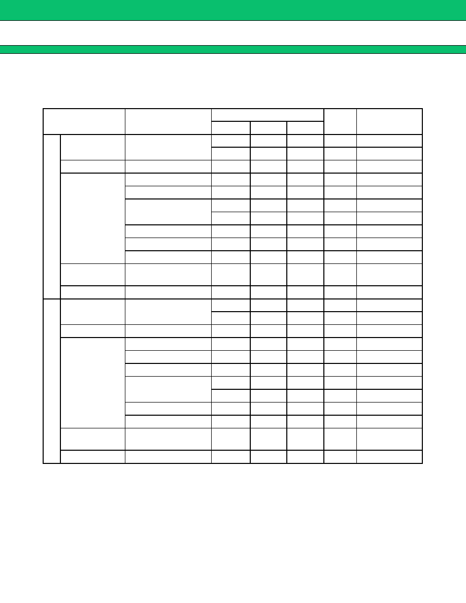
Parameter
Symbol
Rating
Unit
Min.
Max.
Operating temperature
Ta
-
30
+
85
∞
C
Storage temperature
Tstg
-
40
+
100
∞
C
Maximum input power
P
IN
Depends on each design.
See "
s
ELECTRICAL CHARACTERISTICS".
Input DC voltage
-
5
+
5
V
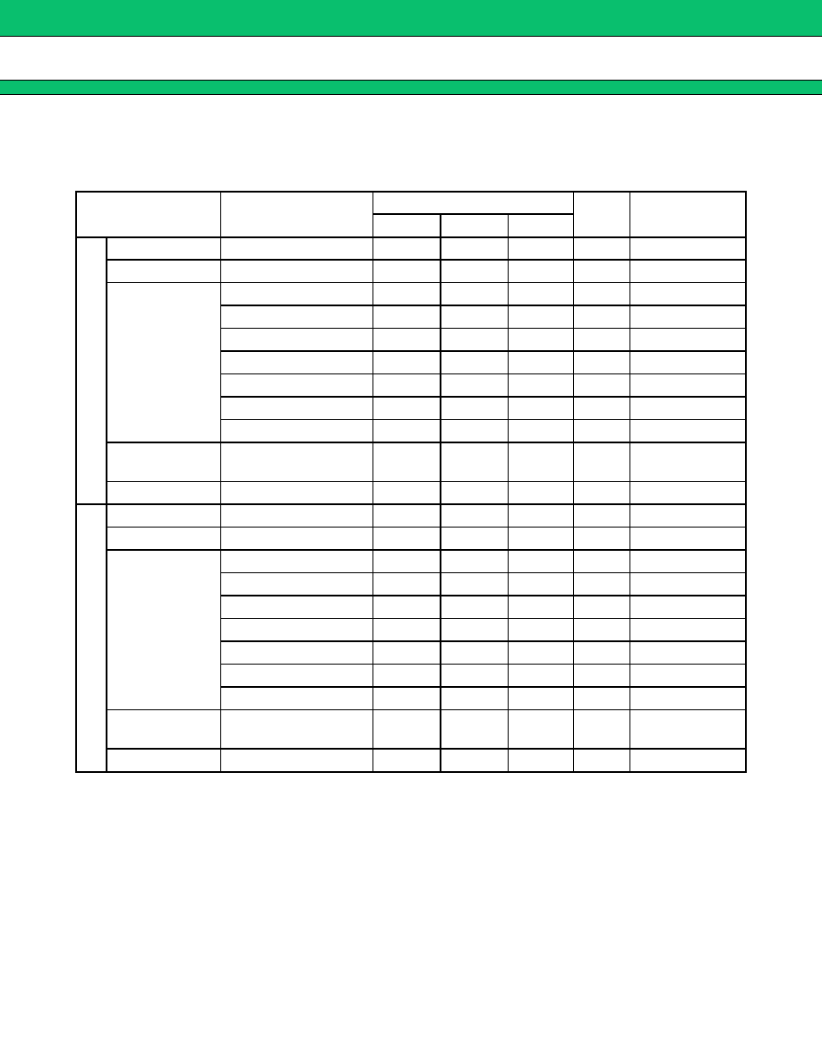
Parameter
Symbol
Value
Unit
Min.
Max.
Operating temperature
Ta
-
30
+
85
∞
C
G5/G6 Series
4
s
s
s
s
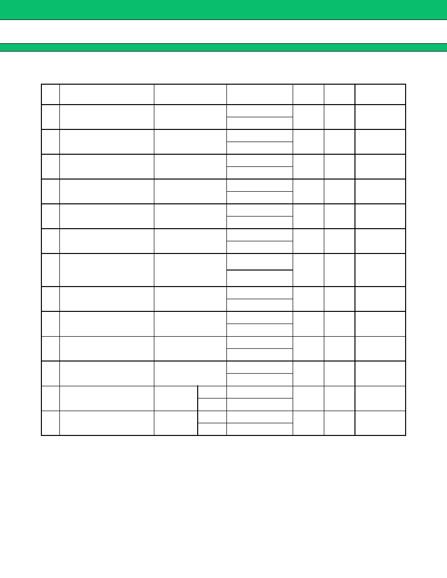
STANDARD FREQUENCIES
No.
Part number
System
Frequency (MHz)
Part
symbol
Input/
Output
Remarks
1
FAR-G5CN-942M50-D296
PDC800 Tx
893 to 898 MHz
96
1 in/
2 out
3.0
◊
3.0 mm
925 to 960 MHz
2
FAR-G5CN-877M50-D292
PDC800 Rx
810 to 843 MHz
92
1 in/
2 out
3.0
◊
3.0 mm
870 to 885 MHz
3
FAR-G6CH-1G8800-L214
AMPS/TDMA/CDMA
+
PCS Tx
824 to 849 MHz
14
2 in/
2 out
3.8
◊
3.8 mm
1850 to 1910 MHz
4
FAR-G6CH-1G9600-L215
AMPS/TDMA/CDMA
+
PCS Rx
869 to 894 MHz
15
2 in/
2 out
3.8
◊
3.8 mm
1930 to 1990 MHz
5
FAR-G6CH-1G7475-L216
GSM
+
PCN Tx
890 to 915 MHz
16
2 in/
2 out
3.8
◊
3.8 mm
1710 to 1785 MHz
6
FAR-G6CH-1G8425-L217
GSM
+
PCN Rx
935 to 960 MHz
17
2 in/
2 out
3.8
◊
3.8 mm
1805 to 1880 MHz
7
FAR-G6CH-1G8425-L218
EGSM
+
PCN Rx
925 to 960 MHz
18
2 in/
2 out
3.8
◊
3.8 mm
Low insertion
loss type
1805 to 1880 MHz
8
FAR-G6CH-1G8425-L222
EGSM
+
PCN Rx
925 to 960 MHz
22
2 in/
2 out
3.8
◊
3.8 mm
High Aff. type
1805 to 1880 MHz
9
FAR-G6CH-1G8425-L227B EGSM
+
PCN Rx
925 to 960 MHz
27
2 in/
2 out
3.8
◊
3.8 mm
1805 to 1880 MHz
10
FAR-G6CH-1G9600-L228A EGSM
+
PCS Rx
925 to 960 MHz
28
2 in/
2 out
3.8
◊
3.8 mm
1930 to 1990 MHz
11
FAR-G6CH-1G9600-L219
PCN
+
PCS Rx
1805 to 1880 MHz
19
2 in/
2 out
3.8
◊
3.8 mm
1930 to 1990 MHz
12
FAR-G6CN-1G8950-L233
PCS Tx
Split
Low
1850 to 1880 MHz
33
2 in/
2 out
3.0
◊
3.0 mm
High
1880 to 1910 MHz
13
FAR-G6CH-1G9750-L230
PCS Rx
Split
Low
1930 to 1960 MHz
30
2 in/
2 out
3.8
◊
3.8 mm
High
1960 to 1990 MHz
G5/G6 Series
5
s
s
s
s
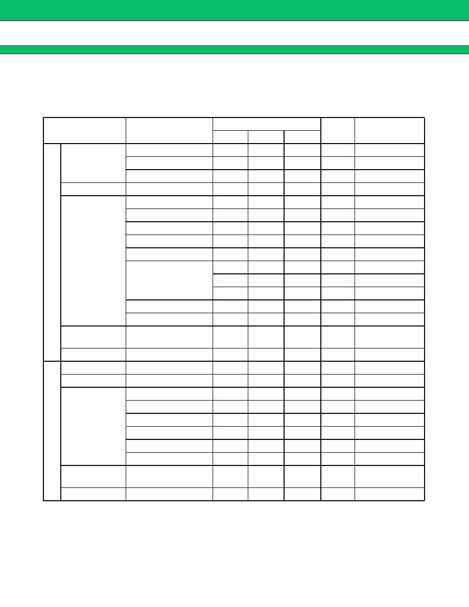
ELECTRICAL CHARACTERISTICS
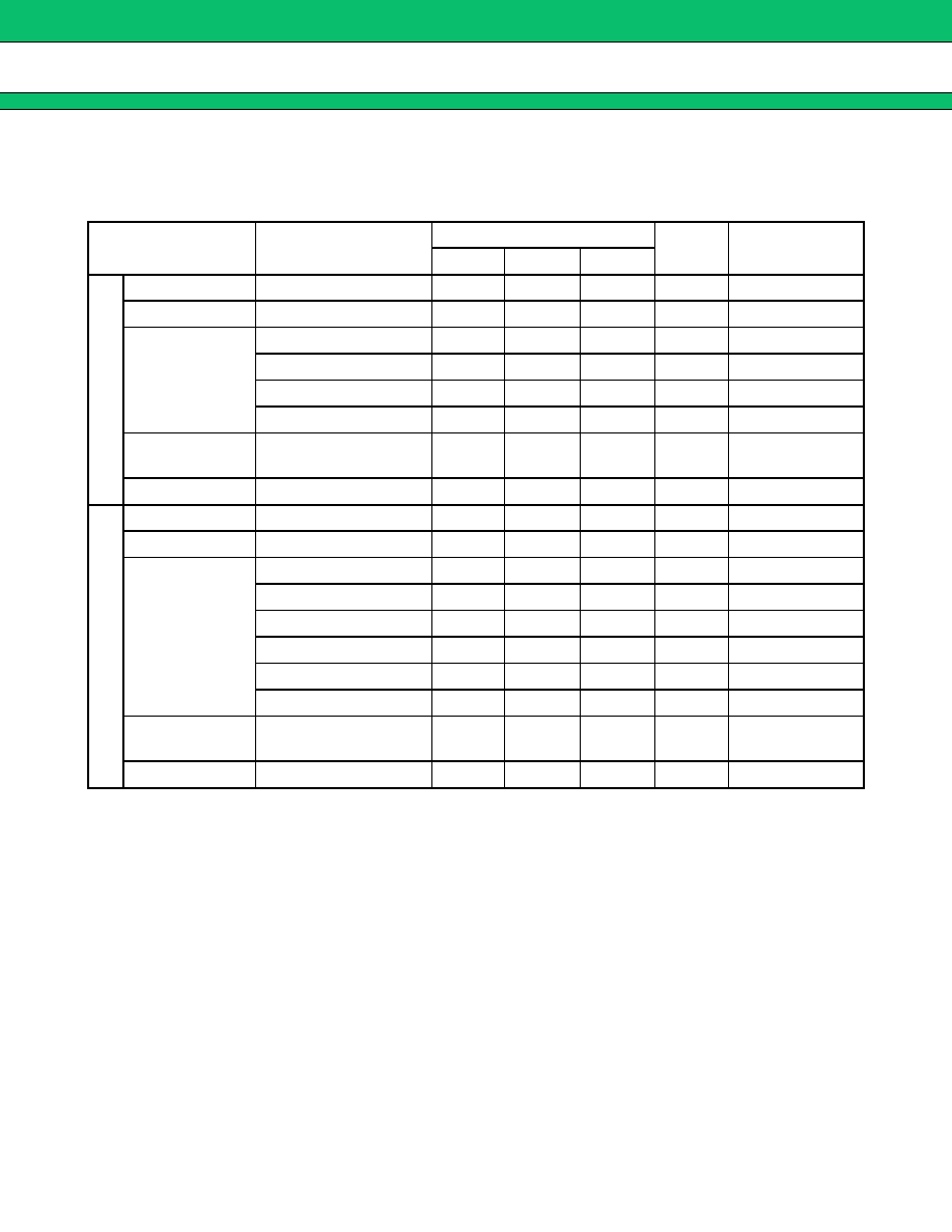
1.
PDC800 (Tx) 1 in/2 out
Part number : FAR-G5CN-942M50-D296
(Ta
=
-
30
∞
C to
+
85
∞
C)
Parameter
Condition
Value
Unit
Remarks
Min.
Typ.
Max.
Insertion Loss
893 to 898 MHz
4.0
dB
-
30 to
+
20
∞
C
893 to 898 MHz
2.7
3.5
dB
+
20 to
+
30
∞
C
893 to 898 MHz
3.5
dB
+
30 to
+
85
∞
C
Inband Ripple
893 to 898 MHz
0.5
1.5
dB
Absolute
Attenuation
520 to 570 MHz
40
48
dB
570 to 640 MHz
35
40
dB
640 to 750 MHz
30
33
dB
750 to 810 MHz
24
28
dB
810 to 870 MHz
15
21
dB
870 to 885 MHz
11
dB
-
30 to
+
20
∞
C
11
18
dB
+
20 to
+
30
∞
C
7
dB
+
30 to
+
85
∞
C
925 to 1000 MHz
10
17
dB
1000 to 1200 MHz
25
31
dB
Inband VSWR
(Return Loss)
893 to 898 MHz
(6.0)
1.9
(10.2)
3.0
(dB)
Max. Input Power
893 to 898 MHz
15
dBm
Insertion Loss
925 to 960 MHz
2.9
4.0
dB
Inband Ripple
925 to 960 MHz
1.6
2.7
dB
Absolute
Attenuation
550 to 650 MHz
38
42
dB
650 to 700 MHz
40
51
dB
700 to 780 MHz
32
36
dB
780 to 885 MHz
23
33
dB
1000 to 1050 MHz
14
17
dB
1050 to 1200 MHz
30
35
dB
Inband VSWR
(Return Loss)
925 to 960 MHz
(6.0)
1.9
(10.2)
3.0
(dB)
Max. Input Power
925 to 960 MHz
15
dBm
Filter 1
Filter 2
G5/G6 Series
6
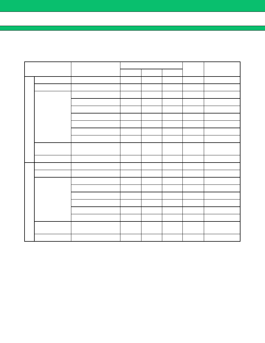
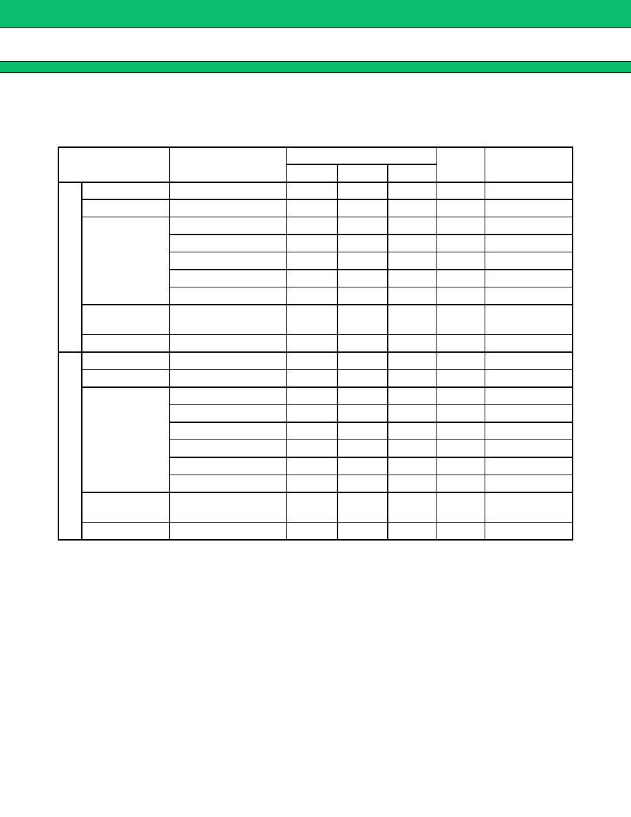
2.
PDC800 (Rx) 1 in/2 out
Part number : FAR-G5CN-877M50-D292
(Ta
=
-
30
∞
C to
+
85
∞
C)
Parameter
Condition
Value
Unit
Remarks
Min.
Typ.
Max.
Insertion Loss
810 to 843 MHz
2.6
4.0
dB
Inband Ripple
810 to 843 MHz
0.8
2.2
dB
Absolute
Attenuation
550 to 585 MHz
40
47
dB
585 to 650 MHz
28
32
dB
650 to 780 MHz
20
24
dB
865 to 889 MHz
16
19
dB
889 to 900 MHz
19
23
dB
900 to 1070 MHz
20
27
dB
1070 to 1110 MHz
30
33
dB
Inband VSWR
(Return Loss)
810 to 828 MHz
(6.5)
2.1
(9.0)
2.8
(dB)
Max. Input Power
810 to 828 MHz
15
dBm
Insertion Loss
870 to 885 MHz
2.7
3.5
dB
Inband Ripple
870 to 885 MHz
0.2
1.0
dB
Absolute
Attenuation
610 to 630 MHz
40
46
dB
630 to 700 MHz
35
40
dB
700 to 840 MHz
20
27
dB
925 to 960 MHz
15
19
dB
960 to 1130 MHz
30
37
dB
1130 to 1145 MHz
32
35
dB
Inband VSWR
(Return Loss)
870 to 885 MHz
(7.4)
1.9
(10.2)
2.5
(dB)
Max. Input Power
870 to 885 MHz
15
dBm
Filter 1
Filter 2
G5/G6 Series
7
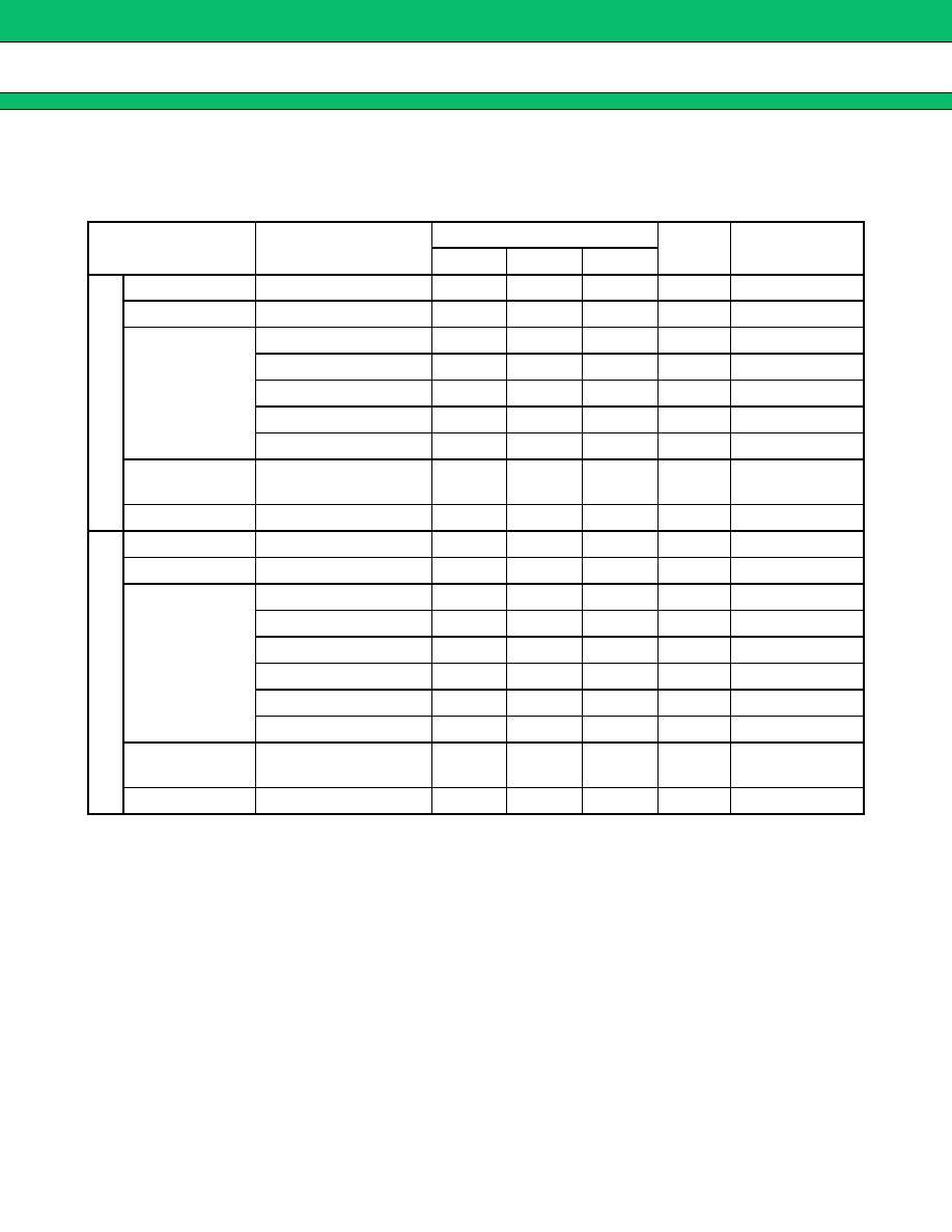
3.
AMPS/TDMA/CDMA Tx
+
+
+
+
PCS Tx (2 in/2 out)
Part number : FAR-G6CH-1G8800-L214
(Ta
=
-
30
∞
C to
+
85
∞
C)
Parameter
Condition
Value
Unit
Remarks
Min.
Typ.
Max.
Insertion Loss
824 to 849 MHz
2.9
3.6
dB
Inband Ripple
824 to 849 MHz
0.9
1.6
dB
Absolute
Attenuation
DC to 800 MHz
40
45
dB
869 to 894 MHz
28
32
dB
1000 to 1500 MHz
40
47
dB
1500 to 2000 MHz
25
33
dB
Inband VSWR
(Return Loss)
824 to 849 MHz
(9.5)
1.6
(12.7)
2.0
(dB)
Max. Input Power
824 to 849 MHz
15
dBm
Insertion Loss
1850 to 1910 MHz
3.2
4.3
dB
Inband Ripple
1850 to 1910 MHz
1.6
2.7
dB
Absolute
Attenuation
DC to 1500 MHz
21
23
dB
1500 to 1800 MHz
23
25
dB
1930 to 1990 MHz
7
17
dB
2000 to 2100 MHz
28
33
dB
2200 to 3000 MHz
19
23
dB
3000 to 4000 MHz
15
19
dB
Inband VSWR
(Return Loss)
1850 to 1910 MHz
(8.1)
1.8
(10.9)
2.3
(dB)
Max. Input Power
1850 to 1910 MHz
13
dBm
Filter 1
Filter 2
G5/G6 Series
8
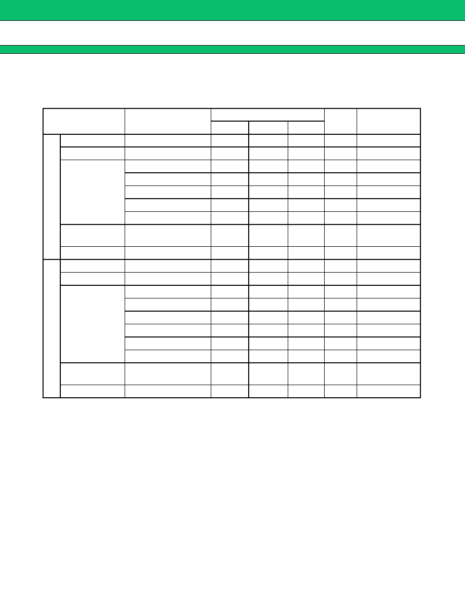
4.
AMPS/TDMA/CDMA Rx
+
+
+
+
PCS Rx (2 in/2 out)
Part number : FAR-G6CH-1G9600-L215
(Ta
=
-
30
∞
C to
+
85
∞
C)
Parameter
Condition
Value
Unit
Remarks
Min.
Typ.
Max.
Insertion Loss
869 to 894 MHz
3.0
3.6
dB
Inband Ripple
869 to 894 MHz
1.0
1.6
dB
Absolute
Attenuation
DC to 800 MHz
42
50
dB
824 to 849 MHz
30
45
dB
920 to 1000 MHz
28
30
dB
1000 to 1500 MHz
40
45
dB
1500 to 2000 MHz
23
32
dB
Inband VSWR
(Return Loss)
869 to 894 MHz
(9.5)
1.5
(14.0)
2.0
(dB)
Max. Input Power
869 to 894 MHz
15
dBm
Insertion Loss
1930 to 1990 MHz
3.2
4.3
dB
Inband Ripple
1930 to 1990 MHz
1.5
2.6
dB
Absolute
Attenuation
DC to 1500 MHz
21
23
dB
1500 to 1850 MHz
23
25
dB
1850 to 1910 MHz
8
25
dB
2040 to 2200 MHz
25
30
dB
2500 to 3000 MHz
20
24
dB
3000 to 4000 MHz
15
18
dB
Inband VSWR
(Return Loss)
1930 to 1990 MHz
(8.1)
1.5
(14.0)
2.3
(dB)
Max. Input Power
1930 to 1990 MHz
13
dBm
Filter 1
Filter 2
G5/G6 Series
9
5.
GSM Tx
+
+
+
+
PCN Tx (2 in/2 out)
Part number : FAR-G6CH-1G7475-L216
(Ta
=
-
30
∞
C to
+
85
∞
C)
Parameter
Condition
Value
Unit
Remarks
Min.
Typ.
Max.
Insertion Loss
890 to 915 MHz
3.1
3.6
dB
Inband Ripple
890 to 915 MHz
1.2
1.7
dB
Absolute
Attenuation
DC to 800 MHz
45
50
dB
800 to 870 MHz
30
43
dB
935 to 960 MHz
28
31
dB
1000 to 1500 MHz
40
45
dB
1500 to 2000 MHz
25
34
dB
Inband VSWR
(Return Loss)
890 to 915 MHz
(9.5)
1.5
(14.0)
2.0
(dB)
Max. Input Power
890 to 915 MHz
15
dBm
Insertion Loss
1710 to 1785 MHz
3.0
4.3
dB
Inband Ripple
1710 to 1785 MHz
1.6
2.9
dB
Absolute
Attenuation
DC to 1500 MHz
17
18
dB
1500 to 1670 MHz
22
26
dB
1805 to 1880 MHz
7
19
dB
1900 to 2000 MHz
25
28
dB
2100 to 3000 MHz
20
24
dB
3000 to 3570 MHz
15
19
dB
Inband VSWR
(Return Loss)
1710 to 1785 MHz
(7.7)
1.8
(10.9)
2.4
(dB)
Max. Input Power
1710 to 1785 MHz
13
dBm
Filter 1
Filter 2

G5/G6 Series
10
6.
GSM Rx
+
+
+
+
PCN Rx (2 in/2 out)
Part number : FAR-G6CH-1G8425-L217
(Ta
=
-
30
∞
C to
+
85
∞
C)
Parameter
Condition
Value
Unit
Remarks
Min.
Typ.
Max.
Insertion Loss
935 to 960 MHz
3.1
3.5
dB
Inband Ripple
935 to 960 MHz
1.1
1.5
dB
Absolute
Attenuation
DC to 800 MHz
45
53
dB
890 to 915 MHz
30
43
dB
980 to 1030 MHz
25
30
dB
1100 to 1500 MHz
40
45
dB
1500 to 2000 MHz
25
36
dB
Inband VSWR
(Return Loss)
930 to 960 MHz
(9.5)
1.6
(12.7)
2.0
(dB)
Max. Input Power
930 to 960 MHz
15
dBm
Insertion Loss
1805 to 1880 MHz
2.8
4.0
dB
Inband Ripple
1805 to 1880 MHz
1.2
2.4
dB
Absolute
Attenuation
DC to 1300 MHz
17
18
dB
1355 to 1430 MHz
17
20
dB
1500 to 1710 MHz
20
22
dB
1710 to 1785 MHz
11
25
dB
1920 to 1980 MHz
20
30
dB
2000 to 3000 MHz
22
25
dB
3000 to 3760 MHz
15
18
dB
Inband VSWR
(Return Loss)
1805 to 1880 MHz
(7.7)
2.0
(9.5)
2.4
(dB)
Max. Input Power
1805 to 1880 MHz
13
dBm
Filter 1
Filter 2

G5/G6 Series
11
7.
EGSM Rx
+
+
+
+
PCN Rx (2 in/2 out)
Part number : FAR-G6CH-1G8425-L218
(Ta
=
-
30
∞
C to
+
85
∞
C)
Parameter
Condition
Value
Unit
Remarks
Min.
Typ.
Max.
Insertion Loss
925 to 960 MHz
2.5
dB
+
20 to
+
30
∞
C
2.2
3.0
dB
-
30 to
+
85
∞
C
Inband Ripple
925 to 960 MHz
0.8
1.6
dB
Absolute
Attenuation
DC to 880 MHz
16
18
dB
880 to 915 MHz
10
dB
+
20 to
+
30
∞
C
5
17
dB
-
30 to
+
85
∞
C
980 to 1200 MHz
13
22
dB
1375 to 1410 MHz
20
24
dB
1850 to 1920 MHz
25
32
dB
2775 to 2880 MHz
15
18
dB
Inband VSWR
(Return Loss)
925 to 960 MHz
(7.4)
2.1
(9.0)
2.5
(dB)
Max. Input Power
925 to 960 MHz
23
dBm
Insertion Loss
1805 to 1880 MHz
3.2
dB
+
20 to
+
30
∞
C
2.7
3.7
dB
-
30 to
+
85
∞
C
Inband Ripple
1805 to 1880 MHz
1.1
2.1
dB
Absolute
Attenuation
DC to 1300 MHz
17
18
dB
1355 to 1430 MHz
18
20
dB
1500 to 1710 MHz
20
22
dB
1710 to 1785 MHz
17
dB
+
20 to
+
30
∞
C
8
25
dB
-
30 to
+
85
∞
C
1920 to 1980 MHz
15
29
dB
3610 to 3760 MHz
15
17
dB
5415 to 5640 MHz
12
17
dB
Inband VSWR
(Return Loss)
1805 to 1880 MHz
(7.7)
2.0
(9.5)
2.4
(dB)
Max. Input Power
1805 to 1880 MHz
13
dBm
Filter 1
Filter 2
G5/G6 Series
12
8.
EGSM Rx
+
+
+
+
PCN Rx (2 in/2 out)
Part number : FAR-G6CH-1G8425-L222
(Ta
=
-
30
∞
C to
+
85
∞
C)
Parameter
Condition
Value
Unit
Remarks
Min.
Typ.
Max.
Insertion Loss
925 to 960 MHz
3.6
4.8
dB
Inband Ripple
925 to 960 MHz
1.6
2.8
dB
Absolute
Attenuation
DC to 800 MHz
40
50
dB
880 to 915 MHz
15
22
dB
980 to 1030 MHz
25
31
dB
1375 to 1410 MHz
40
46
dB
1850 to 1920 MHz
30
44
dB
Inband VSWR
(Return Loss)
925 to 960 MHz
(6.5)
2.3
(8.1)
2.8
(dB)
Max. Input Power
925 to 960 MHz
15
dBm
Insertion Loss
1805 to 1880 MHz
3.4
4.5
dB
Inband Ripple
1805 to 1880 MHz
1.8
2.9
dB
Absolute
Attenuation
DC to 1300 MHz
20
22
dB
1355 to 1430 MHz
21
23
dB
1500 to 1710 MHz
22
25
dB
1710 to 1785 MHz
10
23
dB
1920 to 1980 MHz
25
34
dB
3610 to 3760 MHz
20
36
dB
Inband VSWR
(Return Loss)
1805 to 1880 MHz
(6.5)
2.3
(8.1)
2.8
(dB)
Max. Input Power
1805 to 1880 MHz
13
dBm
Filter 1
Filter 2
G5/G6 Series
13
9.
EGSM Rx
+
+
+
+
PCN Rx (2 in/2 out)
Part number : FAR-G6CH-1G8425-L227B
(Ta
=
-
30
∞
C to
+
85
∞
C)
Parameter
Condition
Value
Unit
Remarks
Min.
Typ.
Max.
Insertion Loss
925 to 960 MHz
3.0
dB
+
20 to
+
30
∞
C
2.7
3.7
dB
-
30 to
+
85
∞
C
Inband Ripple
925 to 960 MHz
1.1
2.1
dB
Absolute
Attenuation
DC to 880 MHz
22
23
dB
880 to 905 MHz
28
32
dB
905 to 915 MHz
11
32
dB
-
30 to
+
30
∞
C
7
dB
+
30 to
+
85
∞
C
980 to 1200 MHz
20
30
dB
1375 to 1410 MHz
30
38
dB
1850 to 1920 MHz
20
26
dB
Inband VSWR
(Return Loss)
925 to 960 MHz
(7.7)
1.9
(10.2)
2.4
(dB)
Max. Input Power
925 to 960 MHz
23
dBm
Insertion Loss
1805 to 1880 MHz
3.5
dB
+
20 to
+
30
∞
C
2.8
3.9
dB
-
30 to
+
85
∞
C
Inband Ripple
1805 to 1880 MHz
1.3
2.4
dB
Absolute
Attenuation
DC to 1300 MHz
17
18
dB
1355 to 1430 MHz
17
19
dB
1600 to 1710 MHz
20
22
dB
1710 to 1785 MHz
20
25
dB
-
30 to
+
30
∞
C
10
dB
+
30 to
+
85
∞
C
1920 to 1980 MHz
20
29
dB
3610 to 3760 MHz
15
19
dB
Inband VSWR
(Return Loss)
1805 to 1880 MHz
(7.7)
1.9
(10.2)
2.4
(dB)
Max. Input Power
1805 to 1880 MHz
13
dBm
Filter 1
Filter 2

G5/G6 Series
14
10. EGSM Rx
+
+
+
+
PCN Rx (2 in/2 out)
Part number : FAR-G6CH-1G9600-L228A
(Ta
=
-
30
∞
C to
+
85
∞
C)
Parameter
Condition
Value
Unit
Remarks
Min.
Typ.
Max.
Insertion Loss
925 to 960 MHz
3.0
dB
+
20 to
+
30
∞
C
2.7
3.7
dB
-
30 to
+
85
∞
C
Inband Ripple
925 to 960 MHz
1.1
2.1
dB
Absolute
Attenuation
DC to 880 MHz
22
23
dB
880 to 905 MHz
28
32
dB
905 to 915 MHz
11
32
dB
-
30 to
+
30
∞
C
7
dB
+
30 to
+
85
∞
C
980 to 1200 MHz
20
dB
-
30 to
+
20
∞
C
25
32
dB
+
20 to
+
85
∞
C
1375 to 1410 MHz
30
38
dB
1850 to 1920 MHz
20
26
dB
Inband VSWR
(Return Loss)
925 to 960 MHz
(7.7)
1.9
(10.2)
2.4
(dB)
Max. Input Power
925 to 960 MHz
23
dBm
Insertion Loss
1930 to 1990 MHz
3.9
dB
+
20 to
+
30
∞
C
3.5
4.2
dB
-
30 to
+
85
∞
C
Inband Ripple
1930 to 1990 MHz
1.9
2.6
dB
Absolute
Attenuation
DC to 1850 MHz
20
22
dB
1850 to 1910 MHz
7
10
dB
-
30 to
+
30
∞
C
5
dB
+
30 to
+
85
∞
C
2010 to 2100 MHz
5
dB
-
30 to
+
20
∞
C
6
10
dB
+
20 to
+
85
∞
C
2500 to 2700 MHz
20
25
dB
3000 to 4000 MHz
15
18
dB
Inband VSWR
(Return Loss)
1930 to 1990 MHz
(7.0)
2.1
(9.0)
2.6
(dB)
Max. Input Power
1930 to 1990 MHz
13
dBm
Filter 1
Filter 2
G5/G6 Series
15
11. PCN Rx
+
+
+
+
PCS Rx (2 in/2 out)
Part number : FAR-G6CH-1G9600-L219
(Ta
=
-
30
∞
C to
+
85
∞
C)
Parameter
Condition
Value
Unit
Remarks
Min.
Typ.
Max.
Insertion Loss
1805 to 1880 MHz
3.1
4.0
dB
Inband Ripple
1805 to 1880 MHz
1.4
2.3
dB
Absolute
Attenuation
DC to 1500 MHz
17
18
dB
1600 to 1710 MHz
22
25
dB
1710 to 1785 MHz
10
24
dB
1920 to 1980 MHz
20
30
dB
2000 to 2400 MHz
25
27
dB
3610 to 3760 MHz
16
18
dB
5415 to 5640 MHz
14
16
dB
Inband VSWR
(Return Loss)
1805 to 1880 MHz
(7.7)
2.0
(9.5)
2.4
(dB)
Max. Input Power
1805 to 1880 MHz
13
dBm
Insertion Loss
1930 to 1990 MHz
3.1
4.3
dB
Inband Ripple
1930 to 1990 MHz
1.2
2.4
dB
Absolute
Attenuation
DC to 1500 MHz
21
23
dB
1500 to 1850 MHz
22
25
dB
1850 to 1910 MHz
8
23
dB
2040 to 2200 MHz
25
28
dB
2500 to 3000 MHz
19
21
dB
3860 to 3980 MHz
16
19
dB
5790 to 5970 MHz
8
11
dB
Inband VSWR
(Return Loss)
1930 to 1990 MHz
(8.1)
1.5
(14.0)
2.3
(dB)
Max. Input Power
1930 to 1990 MHz
13
dBm
Filter 1
Filter 2
G5/G6 Series
16
12. PCS Tx split band (low band
+
+
+
+
high band dual) (2 in/2 out)
Part number : FAR-G6CN-1G8950-L233
(Ta
=
-
30
∞
C to
+
85
∞
C)
Parameter
Condition
Value
Unit
Remarks
Min.
Typ.
Max.
Insertion Loss
1850 to 1880 MHz
2.1
3.2
dB
Inband Ripple
1850 to 1880 MHz
0.4
1.5
dB
Absolute
Attenuation
DC to 1700 MHz
20
23
dB
1700 to 1760 MHz
28
38
dB
1930 to 1960 MHz
30
38
dB
2000 to 2100 MHz
30
35
dB
2100 to 3000 MHz
25
35
dB
Inband VSWR
(Return Loss)
1850 to 1880 MHz
(8.5)
1.4
(15.6)
2.2
(dB)
Max. Input Power
1850 to 1880 MHz
13
dBm
Insertion Loss
1880 to 1910 MHz
2.4
3.2
dB
Inband Ripple
1880 to 1910 MHz
0.6
1.5
dB
Absolute
Attenuation
DC to 1700 MHz
21
24
dB
1700 to 1760 MHz
28
37
dB
1800 to 1830 MHz
15
26
dB
1960 to 1990 MHz
30
37
dB
2000 to 2100 MHz
30
38
dB
2100 to 3000 MHz
25
32
dB
Inband VSWR
(Return Loss)
1880 to 1910 MHz
(8.5)
1.5
(14.0)
2.2
(dB)
Max. Input Power
1880 to 1910 MHz
13
dBm
Filter 1
Filter 2

G5/G6 Series
17
`
13. PCS Rx split band (low band + high band dual) (2 in/2 out)
Part number : FAR-G6CH-1G9750-L230
(Ta
=
-
30
∞
C to
+
85
∞
C)
Parameter
Condition
Value
Unit
Remarks
Min.
Typ.
Max.
Insertion Loss
1930 to 1960 MHz
2.4
3.2
dB
Inband Ripple
1930 to 1960 MHz
0.6
1.4
dB
Absolute
Attenuation
DC to 1850 MHz
20
21
dB
1850 to 1880 MHz
30
36
dB
2040 to 2070 MHz
20
30
dB
2500 to 3000 MHz
20
32
dB
Inband VSWR
(Return Loss)
1930 to 1960 MHz
(9.0)
1.7
(11.7)
2.1
(dB)
Max. Input Power
1930 to 1960 MHz
13
dBm
Insertion Loss
1960 to 1990 MHz
2.3
3.2
dB
Inband Ripple
1960 to 1990 MHz
0.5
1.4
dB
Absolute
Attenuation
DC to 1880 MHz
20
21
dB
1880 to 1910 MHz
30
40
dB
2070 to 2100 MHz
20
31
dB
2500 to 3000 MHz
20
31
dB
Inband VSWR
(Return Loss)
1960 to 1990 MHz
(9.0)
1.7
(11.7)
2.1
(dB)
Max. Input Power
1960 to 1990 MHz
13
dBm
Filter 1
Filter 2

G5/G6 Series
18
s
s
s
s
TYPICAL CHARACTERISTICS
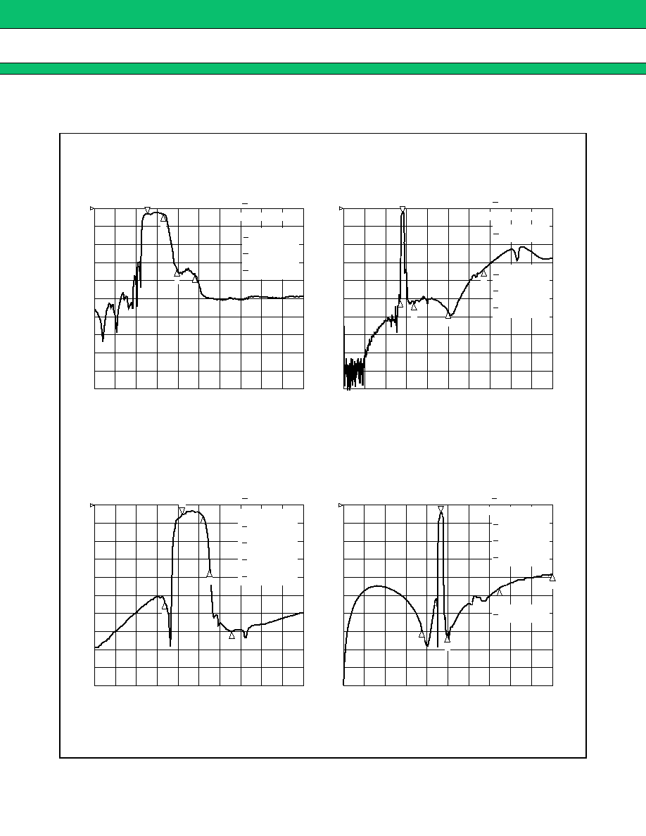
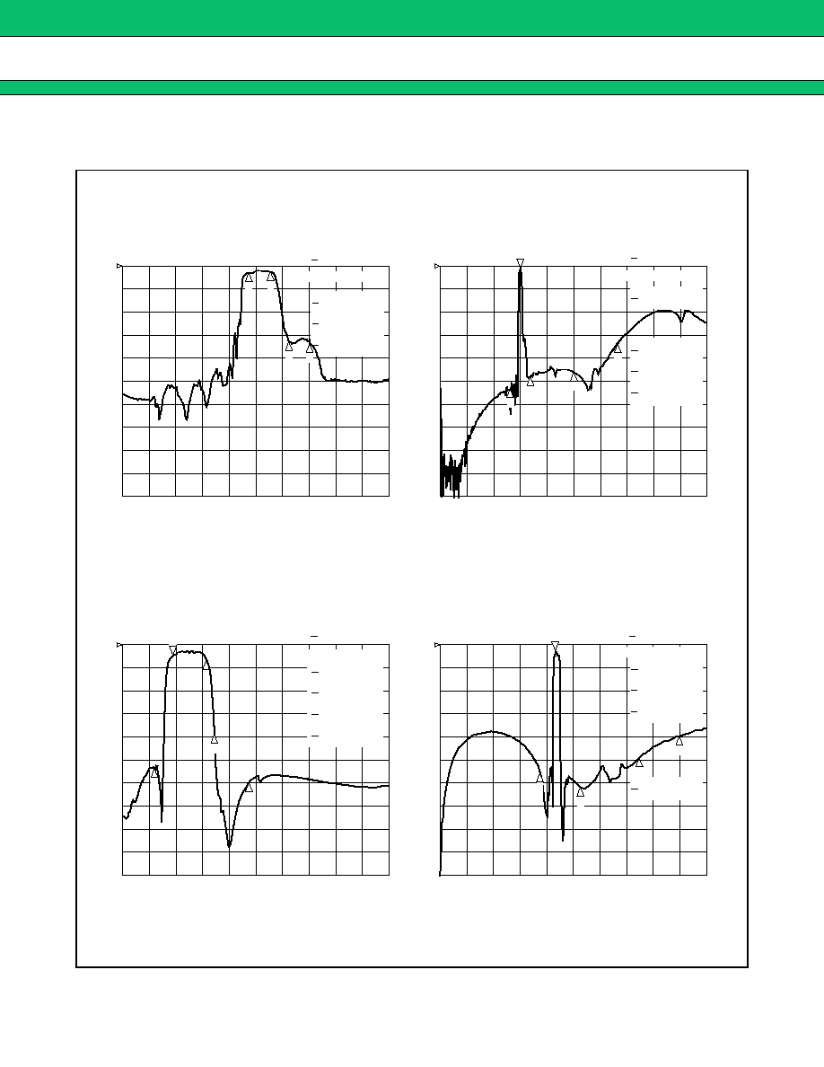
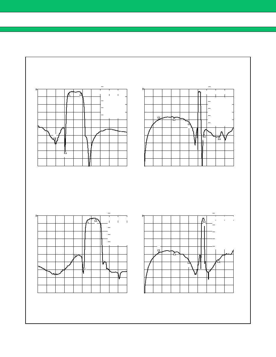
1.
PDC800 (Tx) 1 in/2 out
Part number : FAR-G5CN-942M50-D296
1
:
-
23.066 dB
885 MHz
2
:
-
2.8612 dB
893 MHz
3
:
-
2.8997 dB
898 MHz
4
:
-
17.271 dB
925 MHz
960.000 000 MHz
5
:
-
28.816 dB
REF 0 dB
5 dB
/
S
21
REF 0 dB
5 dB
/
S
21
CENTER 900.000 000 MHz
SPAN 300.000 000 MHz
2
:
-
13.063 dB
942.5 MHz
3
:
-
29.451 dB
1.5 GHz
4
:
-
26.087 dB
2 GHz
1
3
4
895.500 000 MHz
1
:
-
3.0502 dB
START .010 000 MHz
STOP 3 000.000 000 MHz
1
:
-
33.71 dB
885 MHz
2
:
-
27.406 dB
893 MHz
3
:
-
27.095 dB
898 MHz
4
:
-
2.2482 dB
925 MHz
1
5
:
-
2.6652 dB
REF 0 dB
5 dB
/
S
21
CENTER 900.000 000 MHz
SPAN 300.000 000 MHz
4
3
2
2
:
-
1.9154 dB
942.5 MHz
3
:
-
34.254 dB
1.5 GHz
4
:
-
28.783 dB
2 GHz
895.500 000 MHz
1
:
-
26.96 dB
REF 0 dB
5 dB
/
S
21
START .010 000 MHz
STOP 3 000.000 000 MHz
3
5
4
3
1
4
5
2
2
1
2
960.000 000 MHz
Filter 1 (Passband : 893 to 898 MHz)
Filter 2 (Passband : 925 to 960 MHz)

G5/G6 Series
19
2.
PDC800 (Rx) 1 in/2 out
Part number : FAR-G5CN-877M50-D292
2
:
-
2.4868 dB
843 MHz
3
:
-
20.89 dB
870 MHz
4
:
-
19.238 dB
885 MHz
1
2
3
4
809.930 000 MHz
1
:
-
2.3702 dB
REF 0 dB
5 dB
/
S
21
START 500.000 000 MHz
STOP 1 200.000 000 MHz
2
: -
34.35 dB
843 MHz
3
:
-
2.4709 dB
870 MHz
4
:
-
2.4825 dB
885 MHz
1
4
3
2
809.930 000 MHz
1
:
-
33.929 dB
REF 0 dB
5 dB
/
S
21
START 500.000 000 MHz
STOP 1 200.000 000 MHz
1
:
-
37.593 dB
826.5 MHz
3
:
-
32.036 dB
1.5 GHz
4
:
-
27.043 dB
2 GHz
2
1
3
4
877.500 000 MHz
2
:
-
2.7945 dB
REF 0 dB
5 dB
/
S
21
START .030 000 MHz
STOP 3 000.000 000 MHz
2
:
-
18.27 dB
877.5 MHz
3
:
-
28.707 dB
1.5 GHz
4
:
-
24.673 dB
2 GHz
1
3
4
2
826.500 000 MHz
1
:
-
2.3932 dB
REF 0 dB
5 dB
/
S
21
START .030 000 MHz
STOP 3 000.000 000 MHz
Filter 1 (Passband : 810 to 843 MHz)
Filter 2 (Passband : 870 to 885 MHz)
G5/G6 Series
20
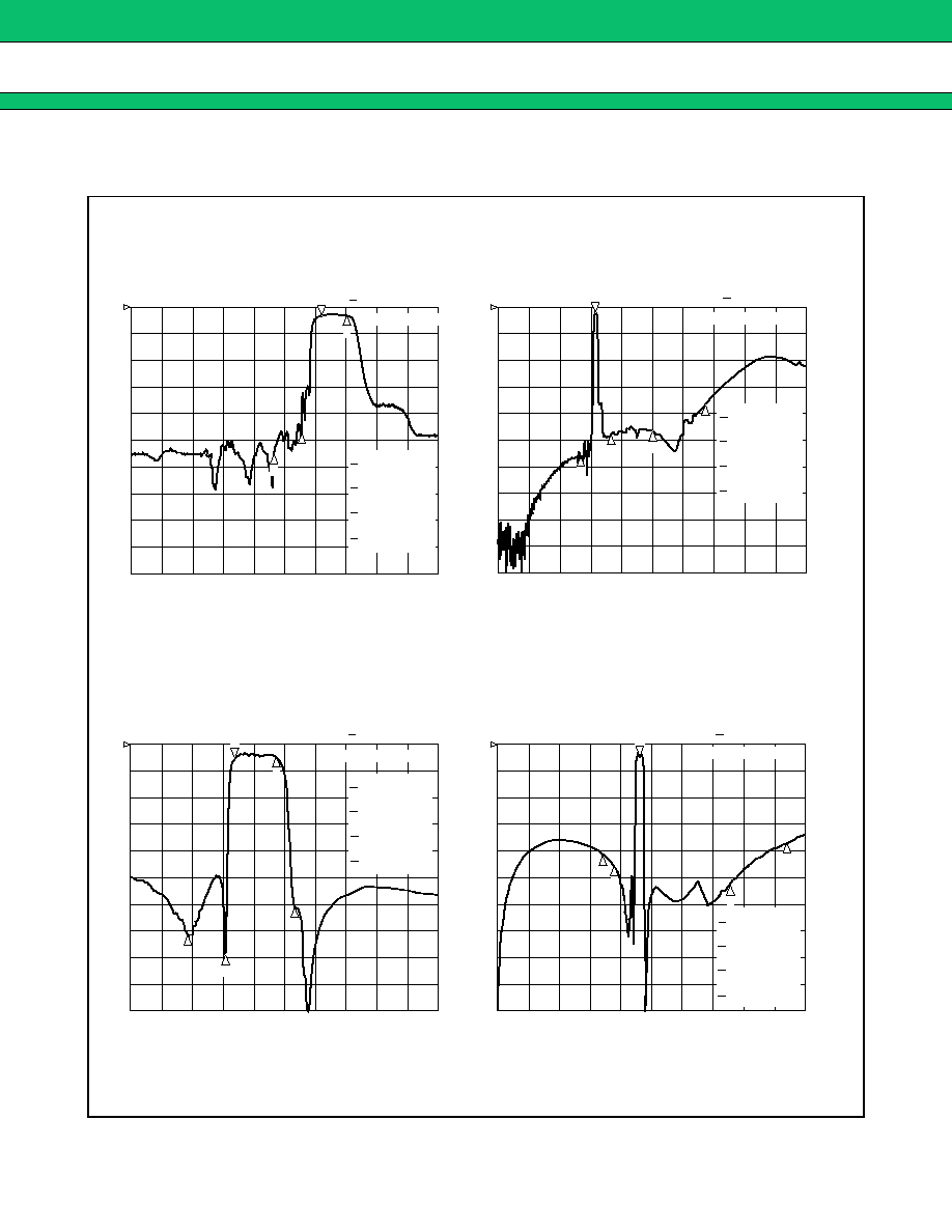
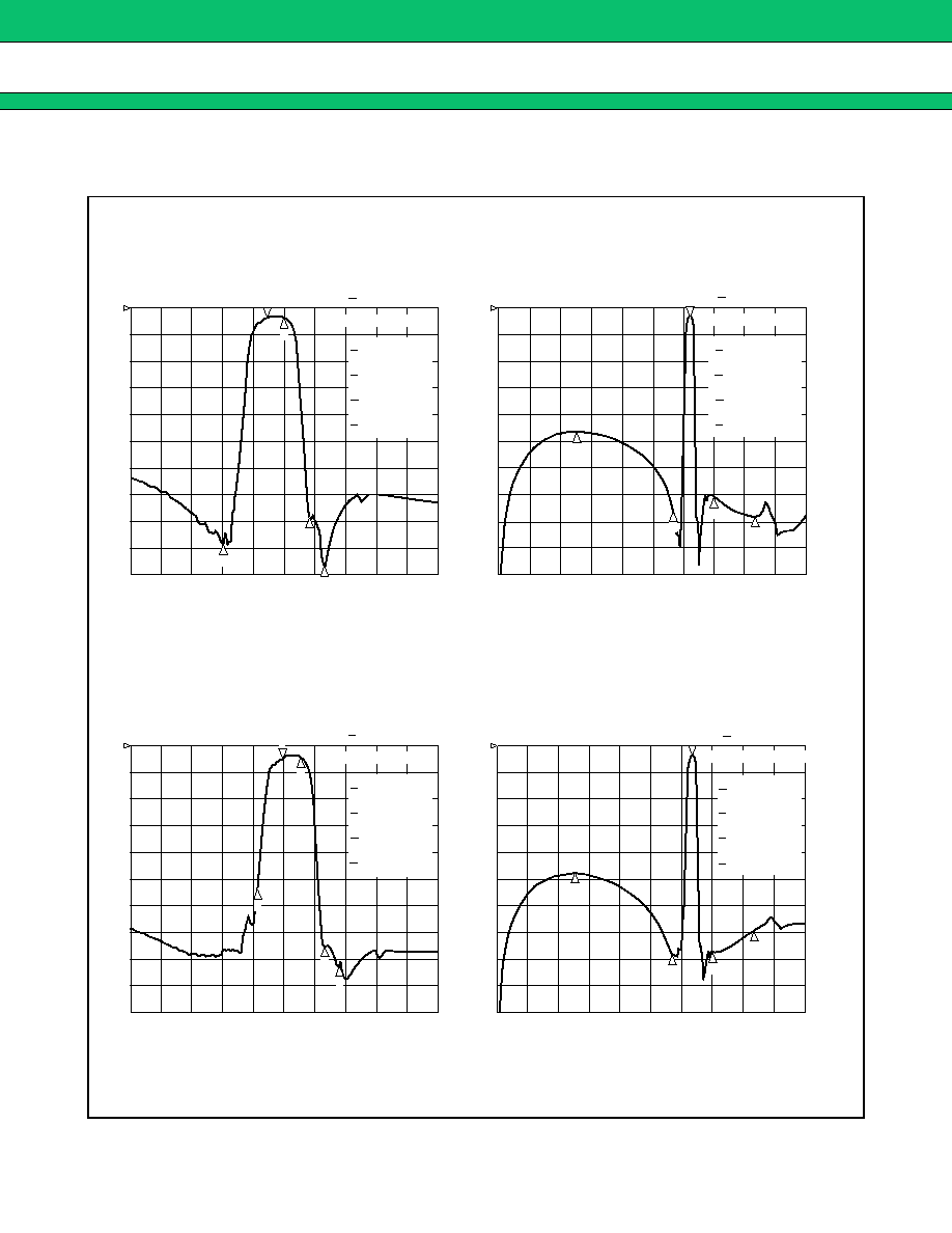
3.
AMPS/TDMA/CDMA Tx
+
+
+
+
PCS Tx (2 in/2 out)
Part number : FAR-G6CH-1G8800-L214
2
:
-
2.696 dB
849 MHz
3
:
-
33.248 dB
869 MHz
4
:
-
36.137 dB
894 MHz
824.000 000 MHz
1
:
-
2.8526 dB
REF 0 dB
5 dB
/
S
21
REF 0 dB
10 dB
/
S
21
CENTER 900.000 000 MHz
SPAN 300.000 000 MHz
2
:
-
50.618 dB
800 MHz
3
:
-
50.711 dB
1 GHz
4
:
-
57.026 dB
1.5 GHz
5
:
-
33.176 dB
2 GHz
1
3
4
5
836.500 000 MHz
1
:
-
2.071 dB
START .010 000 MHz
STOP 3 000.000 000 MHz
2
:
-
3.2178 dB
1.91 GHz
3
:
-
18.115 dB
1.93 GHz
4
:
-
34.751 dB
1.99 GHz
5
:
-
26.401 dB
1.8 GHz
5
1
:
-
2.9114 dB
REF 0 dB
5 dB
/
S
21
CENTER 1 900.000 000 MHz SPAN 600.000 000 MHz
4
2
2
:
-
33.929 dB
1.5 GHz
3
:
-
35.782 dB
2 GHz
4
:
-
22.985 dB
3 GHz
5
:
-
18.507 dB
4 GHz
1 880.000 000 MHz
1
:
-
1.6765 dB
REF 0 dB
5 dB
/
S
21
START .010 000 MHz
STOP 4 000.000 000 MHz
1
4
5
2
3
4
1
1
1 850.000 000 MHz
2
3
2
3
Filter 1 (Passband : 824 to 849 MHz)
Filter 2 (Passband : 1850 to 1910 MHz)

G5/G6 Series
21
4.
AMPS/TDMA/CDMA Rx
+
+
+
+
PCS Rx (2 in/2 out)
Part number : FAR-G6CH-1G9600-L215
2
:
-
2.6918 dB
894 MHz
3
:
-
55.878 dB
824 MHz
4
:
-
45.214 dB
849 MHz
869.000 000 MHz
1
:
-
3.0418 dB
REF 0 dB
10 dB
/
S
21
REF 0 dB
10 dB
/
S
21
CENTER 900.000 000 MHz
SPAN 300.000 000 MHz
2
:
-
61.845 dB
800 MHz
3
:
-
50.486 dB
1 GHz
4
:
-
52.641 dB
1.5 GHz
5
:
-
32.628 dB
2 GHz
1
3
4
5
881.500 000 MHz
1
:
-
2.1702 dB
START .010 000 MHz
STOP 3 000.000 000 MHz
2
:
-
1.9852 dB
1.99 GHz
3
:
-
27.122 dB
1.85 GHz
4
:
-
35.275 dB
1.91 GHz
5
:
-
31.864 dB
2.04 GHz
5
1
:
-
3.2146 dB
REF 0 dB
5 dB
/
S
21
CENTER 1 900.000 000 MHz SPAN 600.000 000 MHz
2
2
:
-
29.000 dB
1.5 GHz
3
:
-
33.848 dB
2.2 GHz
4
:
-
24.297 dB
3 GHz
5
:
-
18.222 dB
4 GHz
1 960.000 000 MHz
1
:
-
1.8239 dB
REF 0 dB
5 dB
/
S
21
START .010 000 MHz
STOP 4 000.000 000 MHz
1
4
5
2
1
1
1 930.000 000 MHz
3
2
3
3
4
2
4
Filter 1 (Passband : 869 to 894 MHz)
Filter 2 (Passband : 1930 to 1960 MHz)
G5/G6 Series
22
5.
GSM Tx
+
+
+
+
PCN Tx (2 in/2 out)
Part number : FAR-G6CH-1G7475-L216
2
:
-
2.491 dB
915 MHz
3
:
-
31.182 dB
935 MHz
4
:
-
33.746 dB
960 MHz
890.000 000 MHz
1
:
-
3.0466 dB
REF 0 dB
10 dB
/
S
21
REF 0 dB
10 dB
/
S
21
CENTER 900.000 000 MHz
SPAN 300.000 000 MHz
2
:
-
52.138 dB
800 MHz
3
:
-
48.081 dB
1 GHz
4
:
-
45.746 dB
1.5 GHz
5
:
-
34.159 dB
2 GHz
1
3
4
5
902.500 000 MHz
1
:
-
2.1467 dB
START .010 000 MHz
STOP 3 000.000 000 MHz
2
:
-
2.9564 dB
1.785 GHz
3
:
-
19.272 dB
1.805 GHz
4
:
-
30.126 dB
1.88 GHz
5
:
-
26.385 dB
1.67 GHz
5
1
:
-
2.6748 dB
REF 0 dB
5 dB
/
S
21
CENTER 1 900.000 000 MHz SPAN 600.000 000 MHz
2
2
:
-
27.673 dB
1.5 GHz
3
:
-
30.86 dB
2.1 GHz
4
:
-
24.523 dB
3 GHz
5
:
-
19.732 dB
3.57 GHz
1 747.500 000 MHz
1
:
-
1.7737 dB
REF 0 dB
5 dB
/
S
21
START .010 000 MHz
STOP 4 000.000 000 MHz
1
4
5
1
2
1
1 710.000 000 MHz
3
3
4
4
2
3
2
Filter 1 (Passband : 890 to 915 MHz)
Filter 2 (Passband : 1710 to 1785 MHz)
G5/G6 Series
23
6.
GSM Rx
+
+
+
+
PCN Rx (2 in/2 out)
Part number : FAR-G6CH-1G8425-L217
2
:
-
2.9262 dB
960 MHz
3
:
-
55.714 dB
890 MHz
4
:
-
46.919 dB
915 MHz
5
:
-
30.292 dB
980 MHz
1
2
935.000 000 MHz
1
:
-
3.0211 dB
REF 0 dB
10 dB
/
S
21
REF 0 dB
10 dB
/
S
21
CENTER 900.000 000 MHz
SPAN 300.000 000 MHz
2
:
-
55.758 dB
800 MHz
3
:
-
47.639 dB
1.1 GHz
4
:
-
46.397 dB
1.5 GHz
5
:
-
36.882 dB
2 GHz
1
3
4
5
2
947.500 000 MHz
1
:
-
2.3038 dB
START .010 000 MHz
STOP 3 000.000 000 MHz
4
3
2
:
-
2.2673 dB
1.88 GHz
3
:
-
35.916 dB
1.71 GHz
4
:
-
39.262 dB
1.785 GHz
5
:
-
30.711 dB
1.92 GHz
1
2
1 805.000 000 MHz
1
:
-
2.7307 dB
REF 0 dB
5 dB
/
S
21
CENTER 1 900.000 000 MHz
SPAN 600.000 000 MHz
4
5
3
2
:
-
20.508 dB
1.355 GHz
3
:
-
22.449 dB
1.5 GHz
4
:
-
26.603 dB
3 GHz
5
:
-
18.214 dB
3.76 GHz
1 842.500 000 MHz
1
:
-
2.3976 dB
REF 0 dB
5 dB
/
S
21
START .010 000 MHz
STOP 4 000.000 000 MHz
1
2
4
5
3
Filter 1 (Passband : 935 to 960 MHz)
Filter 2 (Passband : 1805 to 1880 MHz)
G5/G6 Series
24
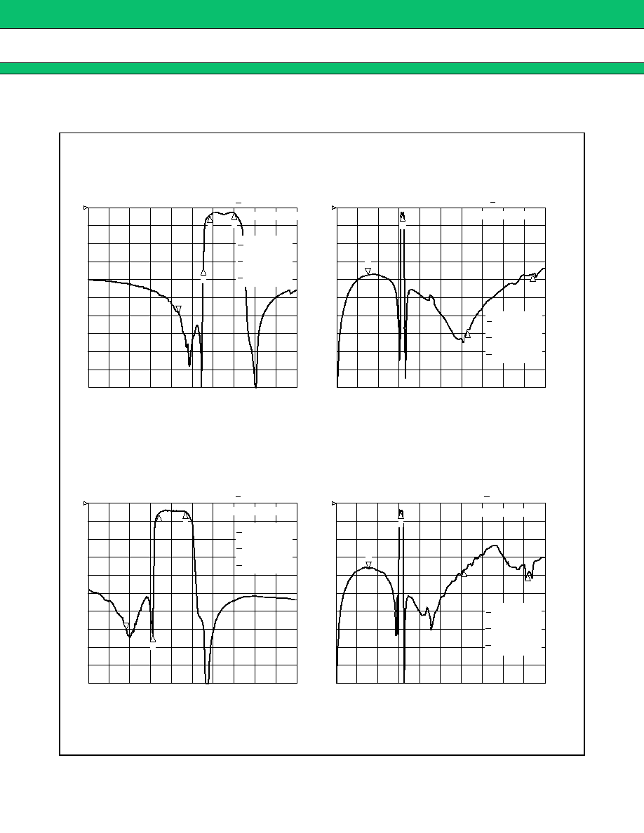
7.
EGSM Rx
+
+
+
+
PCN Rx (2 in/2 out)
Part number : FAR-G6CH-1G8425-L218
2
:
-
17.088 dB
915 MHz
3
:
-
2.2237 dB
925 MHz
4
:
-
1.6333 dB
960 MHz
1
2
880.000 000 MHz
1
:
-
29.514 dB
REF 0 dB
5 dB
/
S
21
REF 0 dB
5 dB
/
S
21
CENTER 900.000 000 MHz
SPAN 300.000 000 MHz
2
:
-
1.7528 dB
942.5 MHz
3
:
-
33.969 dB
1.885 GHz
4
:
-
18.422 dB
2.827 GHz
1
3
4
2
471.250 000 MHz
1
:
-
18.68 dB
START .010 000 MHz
STOP 3 000.000 000 MHz
4
3
1
:
-
35.275 dB
REF 0 dB
5 dB
/
S
21
CENTER 1 900.000 000 MHz
SPAN 600.000 000 MHz
2
:
-
1.9977 dB
1.842 GHz
3
:
-
18.487 dB
3.685 GHz
4
:
-
19.316 dB
5.527 GHz
921.250 000 MHz
1
:
-
18.215 dB
REF 0 dB
5 dB
/
S
21
START .010 000 MHz
STOP 6 000.000 000 MHz
3
1
2
4
1 710.000 000 MHz
2
:
-
36.285 dB
1.785 GHz
3
:
-
2.7392 dB
1.805 GHz
4
:
-
2.0623 dB
1.88 GHz
4
3
2
1
Filter 1 (Passband : 925 to 960 MHz)
Filter 2 (Passband : 1805 to 1880 MHz)
G5/G6 Series
25
8.
EGSM Rx
+
+
+
+
PCN Rx (2 in/2 out)
Part number : FAR-G6CH-1G8425-L222
2
:
-
3.593 dB
960 MHz
3
:
-
50.515 dB
880 MHz
4
:
-
25.943 dB
915 MHz
1
2
925.000 000 MHz
1
:
-
3.3782 dB
REF 0 dB
10 dB
/
S
21
REF 0 dB
10 dB
/
S
21
CENTER 950.000 000 MHz
SPAN 300.000 000 MHz
2
:
-
59.978 dB
800 MHz
3
:
-
47.957 dB
1.2 GHz
4
:
-
46.512 dB
1.392 GHz
5
:
-
48.368 dB
1.855 GHz
1
3
4
5
2
942.500 000 MHz
1
:
-
2.5069 dB
START .010 000 MHz
STOP 3 000.000 000 MHz
3
2
:
-
2.1905 dB
1.88 GHz
3
:
-
39.485 dB
1.71 GHz
4
:
-
23.12 dB
1.785 GHz
5
:
-
37.335 dB
1.92 GHz
1
2
1 805.000 000 MHz
1
:
-
3.4079 dB
REF 0 dB
5 dB
/
S
21
CENTER 1 900.000 000 MHz
SPAN 600.000 000 MHz
4
5
3
2
:
-
24.19 dB
1.392 GHz
3
:
-
25.726 dB
1.5 GHz
4
:
-
36.317 dB
3 GHz
5
:
-
41.105 dB
3.685 GHz
1 842.500 000 MHz
1
:
-
1.8618 dB
REF 0 dB
5 dB
/
S
21
START 50.000 000 MHz
STOP 4 000.000 000 MHz
3
1
2
4
5
4
Filter 1 (Passband : 925 to 960 MHz)
Filter 2 (Passband : 1805 to 1880 MHz)

G5/G6 Series
26
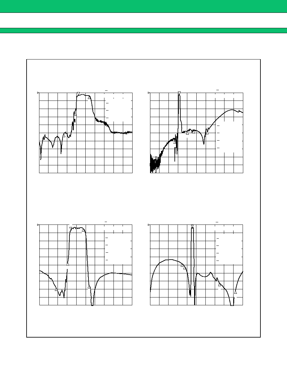
9.
EGSM Rx
+
+
+
+
PCN Rx (2 in/2 out)
Part number : FAR-G6CH-1G8425-L227B
2
:
-
1.933 dB
960 MHz
3
:
-
41.175 dB
880 MHz
4
:
-
36.157 dB
915 MHz
5
:
-
30.825 dB
980 MHz
1
2
925.000 000 MHz
1
:
-
2.61 dB
REF 0 dB
5 dB
/
S
21
REF 0 dB
5 dB
/
S
21
CENTER 950.000 000 MHz
SPAN 300.000 000 MHz
2
:
-
36.855 dB
1.2 GHz
3
:
-
43.206 dB
1.392 GHz
4
:
-
26.605 dB
1.885 GHz
5
:
-
18.698 dB
3 GHz
1
3
4
5
2
942.500 000 MHz
1
:
-
1.7667 dB
START .010 000 MHz
STOP 3 000.000 000 MHz
4
5
3
2
:
-
1.9922 dB
1.88 GHz
3
:
-
32.682 dB
1.71 GHz
4
:
-
35.12 dB
1.785 GHz
5
:
-
32.384 dB
1.92 GHz
1
2
1 805.000 000 MHz
1
:
-
2.7525 dB
REF 0 dB
5 dB
/
S
21
CENTER 1 900.000 000 MHz
SPAN 600.000 000 MHz
4
3
2
:
-
18.336 dB
942.5 MHz
3
:
-
23.109 dB
1.6 GHz
4
:
-
29.253 dB
3 GHz
5
:
-
19.832 dB
3.685 GHz
1 842.500 000 MHz
1
:
-
1.8206 dB
REF 0 dB
5 dB
/
S
21
START 50.000 000 MHz
STOP 4 000.000 000 MHz
3
1
2
4
5
5
Filter 1 (Passband : 925 to 960 MHz)
Filter 2 (Passband : 1805 to 1880 MHz)

G5/G6 Series
27
10. EGSM Rx
+
+
+
+
PCN Rx (2 in/2 out)
Part number : FAR-G6CH-1G9600-L228A
2
:
-
2.0124 dB
960 MHz
3
:
-
42.756 dB
880 MHz
4
:
-
29.411 dB
915 MHz
5
:
-
33.886 dB
980 MHz
1
2
925.000 000 MHz
1
:
-
2.598 dB
REF 0 dB
5 dB
/
S
21
REF 0 dB
5 dB
/
S
21
CENTER 950.000 000 MHz
SPAN 300.000 000 MHz
2
:
-
36.855 dB
1.2 GHz
3
:
-
43.206 dB
1.392 GHz
4
:
-
26.605 dB
1.885 GHz
5
:
-
18.698 dB
3 GHz
1
3
4
5
2
942.500 000 MHz
1
:
-
1.7667 dB
START .010 000 MHz
STOP 3 000.000 000 MHz
4
5
3
2
:
-
2.882 dB
1.99 GHz
3
:
-
27.201 dB
1.85 GHz
4
:
-
10.67 dB
1.91 GHz
5
:
-
10.63 dB
2.01 GHz
1
2
1 930.000 000 MHz
1
:
-
3.4467 dB
REF 0 dB
5 dB
/
S
21
CENTER 1 900.000 000 MHz
SPAN 600.000 000 MHz
4
5
3
2
:
-
23.502 dB
1 GHz
3
:
-
30.967 dB
1.5 GHz
4
:
-
25.266 dB
2.7 GHz
5
:
-
18.573 dB
4 GHz
1 960.000 000 MHz
1
:
-
1.8342 dB
REF 0 dB
5 dB
/
S
21
START .010 000 MHz
STOP 4 000.000 000 MHz
3
1
2
4
5
Filter 1 (Passband : 925 to 960 MHz)
Filter 2 (Passband : 1930 to 1990 MHz)
G5/G6 Series
28
11. PCN Rx
+
+
+
+
PCS Rx (2 in/2 out)
Part number : FAR-G6CH-1G9600-L219
2
:
-
40.042 dB
1.785 GHz
3
: -
2.665
dB
1.805 GHz
4
:
-
2.0468 dB
1.88 GHz
1
2
1 710.000 000 MHz
1
:
-
35.336 dB
REF 0 dB
5 dB
/
S
21
REF 0 dB
5 dB
/
S
21
CENTER 1 900.000 000 MHz
SPAN 600.000 000 MHz
2
:
-
18.458 dB
1 GHz
3
: -
21.476 dB
1.5 GHz
4
:
-
29.357 dB
2 GHz
5
:
-
30.752 dB
2.5 GHz
1
3
4
5
500.000 000 MHz
1
:
-
19.961 dB
START .030 000 MHz
STOP 3 000.000 000 MHz
4
3
2
:
-
32.463 dB
1.91 GHz
3
:
-
3.1341 dB
1.93 GHz
4
:
-
1.842 dB
1.99 GHz
1
2
1 850.000 000 MHz
1
:
-
26.952 dB
REF 0 dB
5 dB
/
S
21
CENTER 1 900.000 000 MHz
SPAN 600.000 000 MHz
4
3
2
:
-
23.541 dB
1 GHz
3
:
-
28.975 dB
1.5 GHz
4
:
-
2.4056 dB
2 GHz
5
:
-
28.152 dB
2.5 GHz
1
2
500.000 000 MHz
1
: -
24.371 dB
REF 0 dB
5 dB
/
S
21
START .030 000 MHz
STOP 3 000.000 000 MHz
4
5
3
2
Filter 1 (Passband : 1805 to 1880 MHz)
Filter 2 (Passband : 1930 to 1990 MHz)
G5/G6 Series
29
12. PCS Tx split band (low band
+
+
+
+
high band dual) (2 in/2 out)
Part number : FAR-G6CN-1G8950-L233
2
:
-
2.0299 dB
1.88 GHz
3
:
-
38.911 dB
1.93 GHz
4
:
-
48.145 dB
1.96 GHz
5
:
-
44.14 dB
1.76 GHz
1
2
1 850.000 000 MHz
1
:
-
1.9431 dB
REF 0 dB
5 dB
/
S
21
REF 0 dB
5 dB
/
S
21
CENTER 1 880.000 000 MHz
SPAN 600.000 000 MHz
2
:
-
23.224 dB
750 MHz
3
:
-
38.618 dB
1.7 GHz
4
:
-
35.44 dB
2.1 GHz
5
:
-
39.19 dB
2.5 GHz
1
3
4
5
2
1 865.000 000 MHz
1
:
-
1.8127 dB
START .030 000 MHz
STOP 3 000.000 000 MHz
5
3
4
2
:
-
2.1745 dB
1.91 GHz
3
:
-
37.657 dB
1.96 GHz
4
:
-
41.046 dB
1.99 GHz
5
:
-
26.235 dB
1.83 GHz
1
2
1 880.000 000 MHz
1
:
-
2.3225 dB
REF 0 dB
5 dB
/
S
21
CENTER 1 880.000 000 MHz
SPAN 600.000 000 MHz
5
2
:
-
24.234 dB
750 MHz
3
:
-
39.277 dB
1.7 GHz
4
:
-
38.691 dB
2.1 GHz
5
:
-
34.735 dB
2.5 GHz
1 895.000 000 MHz
1
:
-
1.986 dB
REF 0 dB
5 dB
/
S
21
START .030 000 MHz
STOP 3 000.000 000 MHz
3
1
2
4
5
4
3
Filter 1 (Passband : 1850 to 1880 MHz)
Filter 2 (Passband : 1930 to 1990 MHz)

G5/G6 Series
30
13. PCS Rx split band (low band + high band dual) (2 in/2 out)
Part number : FAR-G6CH-1G9750-L230
2
:
-
39.937 dB
1.88 GHz
3
: -
2.3954 dB
1.93 GHz
4
:
-
1.8607 dB
1.96 GHz
1
2
1 850.000 000 MHz
1
:
-
36.509 dB
REF 0 dB
5 dB
/
S
21
REF 0 dB
5 dB
/
S
21
CENTER 1 900.000 000 MHz
SPAN 600.000 000 MHz
2
:
-
20.965 dB
1 GHz
3
: -
23.155 dB
1.5 GHz
4
:
-
3.4604 dB
2 GHz
5
:
-
32.985 dB
2.5 GHz
1
3
4
5
500.000 000 MHz
1
:
-
22.5
dB
START .030 000 MHz
STOP 3 000.000 000 MHz
4
3
2
:
-
42.854 dB
1.91 GHz
3
:
-
2.3114 dB
1.96 GHz
4
:
-
1.8591 dB
1.99 GHz
1
2
1 880.000 000 MHz
1
:
-
40.452 dB
REF 0 dB
5 dB
/
S
21
CENTER 1 900.000 000 MHz
SPAN 600.000 000 MHz
4
3
2
:
-
20.884 dB
1 GHz
3
:
-
22.624 dB
1.5 GHz
4
:
-
1.8729 dB
2 GHz
5
:
-
30.985 dB
2.5 GHz
1
2
500.000 000 MHz
1
: -
22.539 dB
REF 0 dB
5 dB
/
S
21
START .030 000 MHz
STOP 3 000.000 000 MHz
4
5
3
2
Filter 1 (Passband : 1930 to 1960 MHz)
Filter 2 (Passband : 1960 to 1990 MHz)

G5/G6 Series
31
s
s
s
s
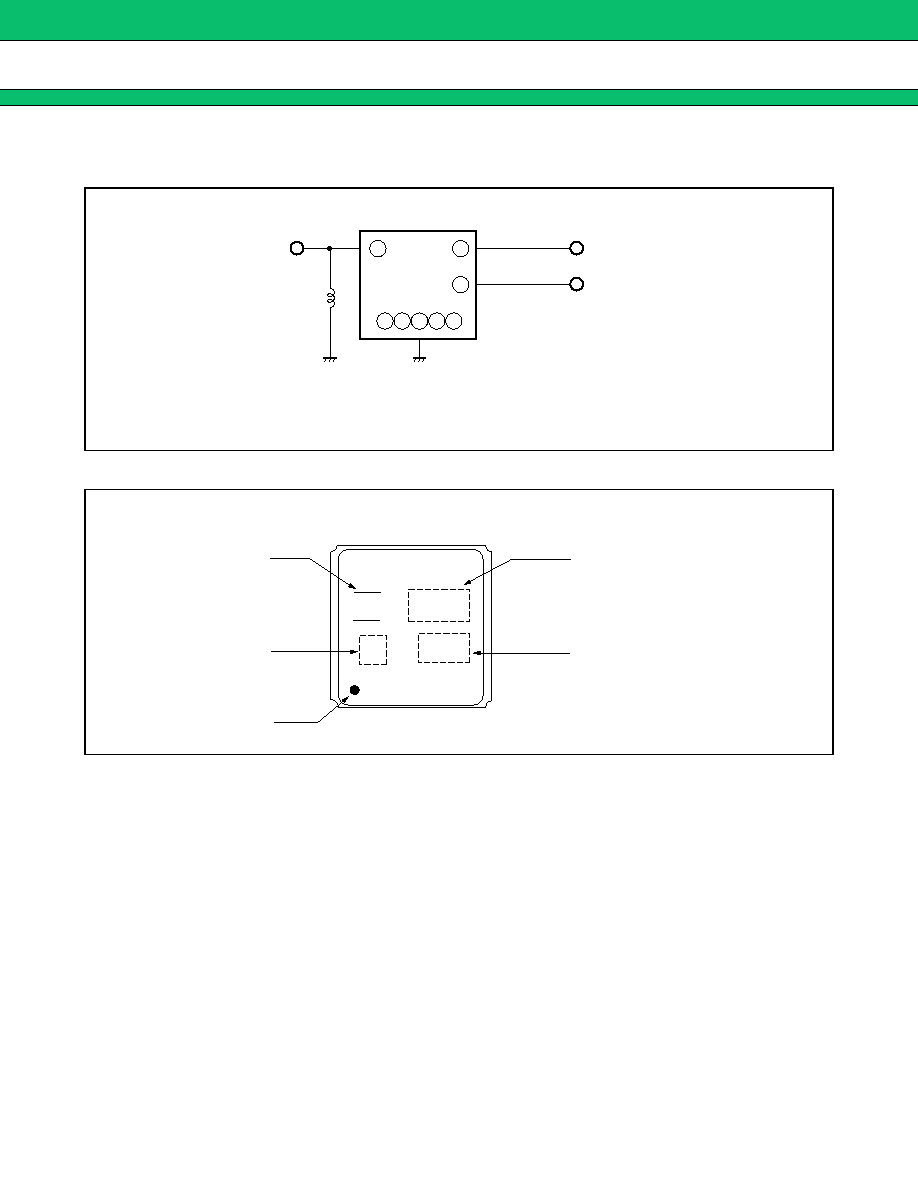
MEASURMENT CIRCUIT
1 in/2 out type (G5CN filters)
2 in/2 out type (G6CH filters)
IN
OUT
*
*
50
IN
OUT
50
1
7
5
8 6
2 3
4
1
7
5
8 6
2 3
4
-
: Pin number
1
8
FAR-G5CN-942M50-D296; 15nH
FAR-G5CN-877M50-D292; 10nH
*:
<
Filter 1
>
<
Filter 2
>
IN
OUT
50
50
IN
OUT
50
50
1
7
5
8 6
2
3
4
3
5
7
8 6
2
1
4
-
: Pin number
1
8
<
Filter 1
>
<
Filter 2
>
G5/G6 Series
32
s
s
s
s
RECOMMENDED EXTARNAL CIRCUIT OF 1 IN/2 OUT TYPE
(G5CN filters)
s
s
s
s
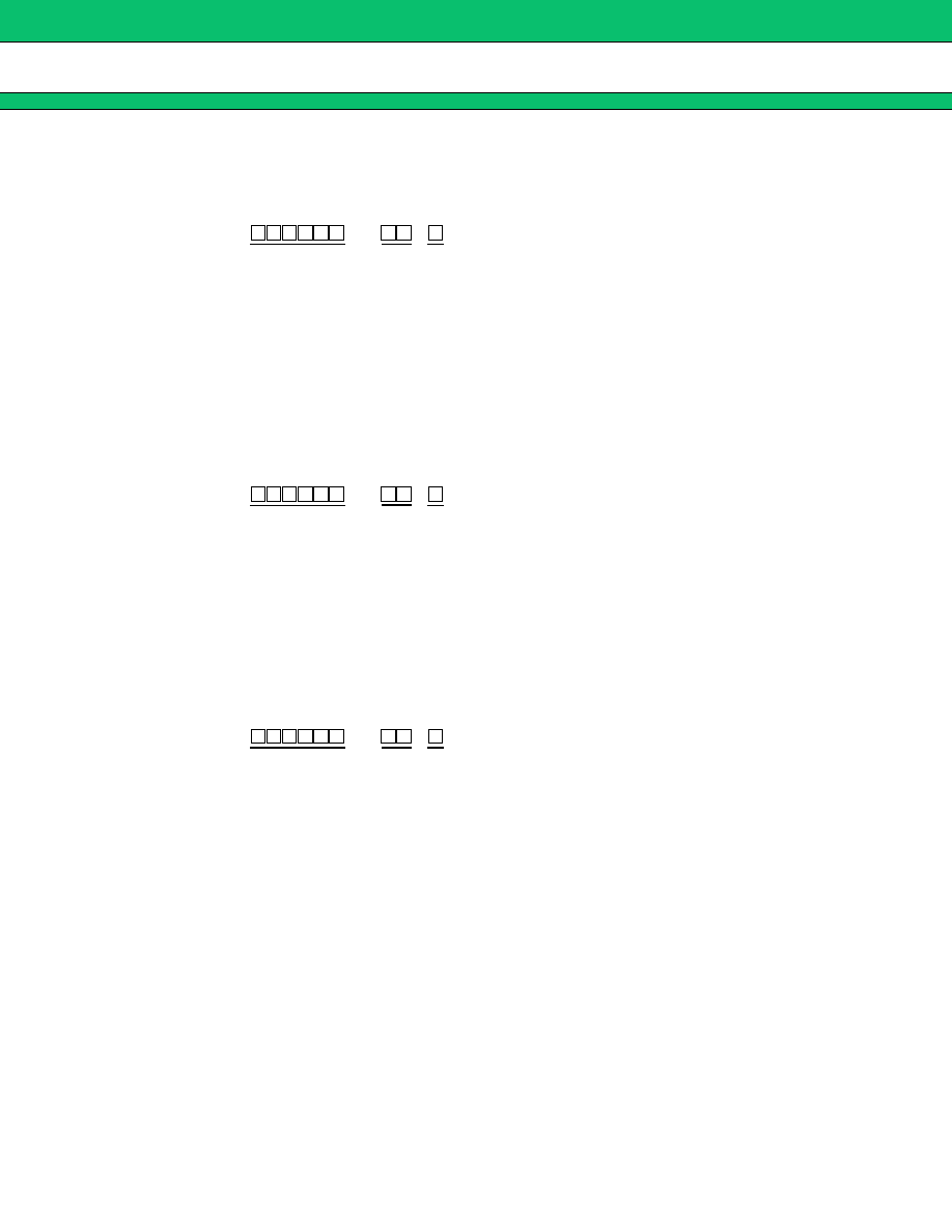
MARKING
7
5
8
6
4
3
2
1
IN
OUT1
OUT2
FAR-G5CN-942M50-D296; 15nH
FAR-G5CN-877M50-D292; 10nH
*:
*
F
B
1 9
3 5
Logo
Date code
Index
Part symbol
Lot number
G5/G6 Series
33
s
s
s
s
PART NUMBER DESIGNATION
[Designation example]
<
G5CN FILTER
>
<
G6CH FILTER
>
<
G6CN FILTER
>
(1) Frequency
: This specifies the nominal center frequency of higher frequency side using six
alphanumeric.
M (for MHz) indicates the decimal point.
[Example] 877M50
877.5 MHz
(2) Part symbol : 01 to 99 (Numbers specified by Fujitsu)
(4) Packing
: W; 1 k pcs/reel
V ; 3 k pcs/reel
U ; 5 k pcs/reel
(1) Frequency
: This specifies the nominal center frequency of higher frequency side using six
alphanumeric.
G (for GHz) indicates the decimal point.
[Example] 1G8800
1.88 GHz
(2) Part symbol : 01 to 99 (Numbers specified by Fujitsu)
(4) Packing
: T; 1 k pcs/reel
R; 3 k pcs/reel
(1) Frequency
: This specifies the nominal center frequency of higher frequency side using six
alphanumeric.
G (for GHz) indicates the decimal point.
[Example] 1G8950
1.895 GHz
(2) Part symbol : 01 to 99 (Numbers specified by Fujitsu)
(4) Packing
: W; 1 k pcs/reel
V ; 3 k pcs/reel
U ; 5 k pcs/reel
FAR-G5CN-
-D2
-
(1)
(2) (3)
FAR-G6CH-
-L2
-
(1)
(2) (3)
FAR-G6CN-
-L2
-
(1)
(2) (3)
G5/G6 Series
34
s
s
s
s
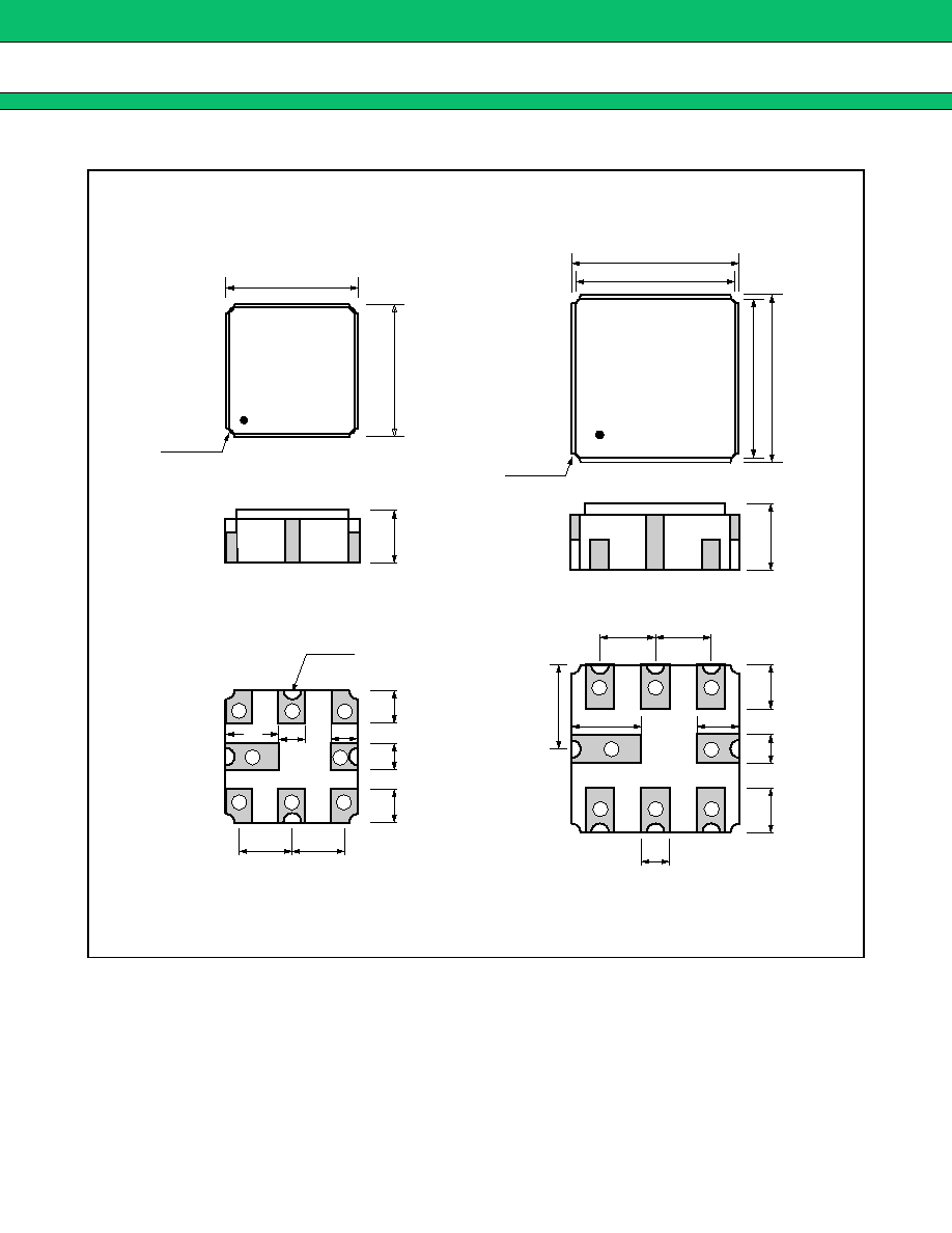
PACKAGE DIMENSIONS
3.0
3.8
3.6
3.8
3.6
3.0
1.2 Max.
1.6 Max.
1.0
1.9
0.64
0.64
1.0
0.75
0.75
0.6
1.2
1.2
1.27
1.27
1.58
0.95
0.6
1.2
4
-
R0.2
4
-
R0.3
4
-
R0.2
1
2
3
7
8
4
6
5
1
2
3
7
8
4
6
5
0.6
<
G5CN package
>
<
G6CN package
>
<
G6CH package
>
Dimensions in mm.

G5/G6 Series
35
s
s
s
s
RECOMMENDED LAND PATTERN
3.0
1.2
0.2
0.6
1.20
1.20
0.7
0.7
1.5
3.0
1.5
0.95
0.75
0.2
3.8
3.8
1.6
1.0
0.70
1.0
1.4
1.27
1.27
0.4
0.4
0.7
Dimensions in mm.
<
G5CN package
>
<
G6CN package
>
<
G6CH package
>
G5/G6 Series
36
s
s
s
s
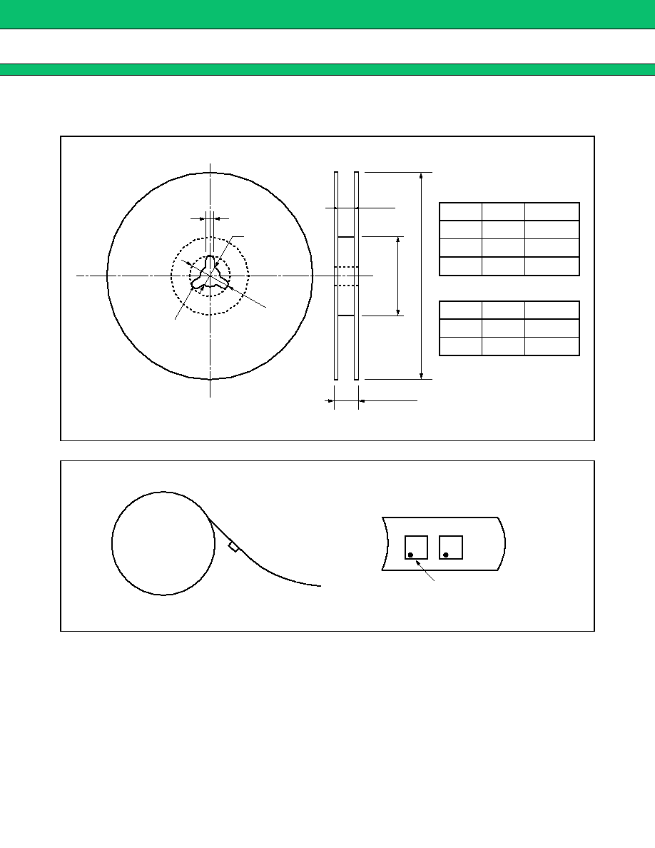
PACKING
1.
Reel type
2.
Packing Style
2
±
0.5
13.0
±
0.2
21
±
0.8
R1.0
18.4
A
80
12.4
+
2.0
-
0.0
<
G5CN filter
>
<
G6CN filter
>
<
G6CH filter
>
Type
A
Volume
-W
250
1 k pcs
-V
250
3 k pcs
-U
250
5 k pcs
Type
A
Volume
-T
250
1 k pcs
-R
330
3 k pcs
Dimensions in mm.
Rulling side
# 1 PIN
Reel side
Rulling side

G5/G6 Series
37
3.
Tape Dimensions
4.
Peel strength of top cover tape
4.0
±
0.1
2.0
±
0.1
5.5
±
0.1
3.3
±
0.1
1.5
+
0.1
-
0
1.5
0.3
12.0
±
0.3
8.0
±
0.1
1.75
±
0.1
1.5
3.3
±
0.1
4.0
±
0.1
2.0
±
0.1
5.5
±
0.1
4.2
±
0.1
1.5
+
0.1
-
0
1.6
0.3
12.0
±
0.3
8.0
±
0.1
1.75
±
0.1
1.8
4.2
±
0.1
<
G5CN filters
>
<
G6CH filters
>
Dimensions in mm.
165 to 180
∞
Direction of pulling
Speed 300 mm/min
Embossment carrier type tape
Peel off by the force of 0.1 N to 0.7 N under the
condition at the right.
(Conforms to JIS C 0806 section 5.2)
G5/G6 Series
38
s
s
s
s
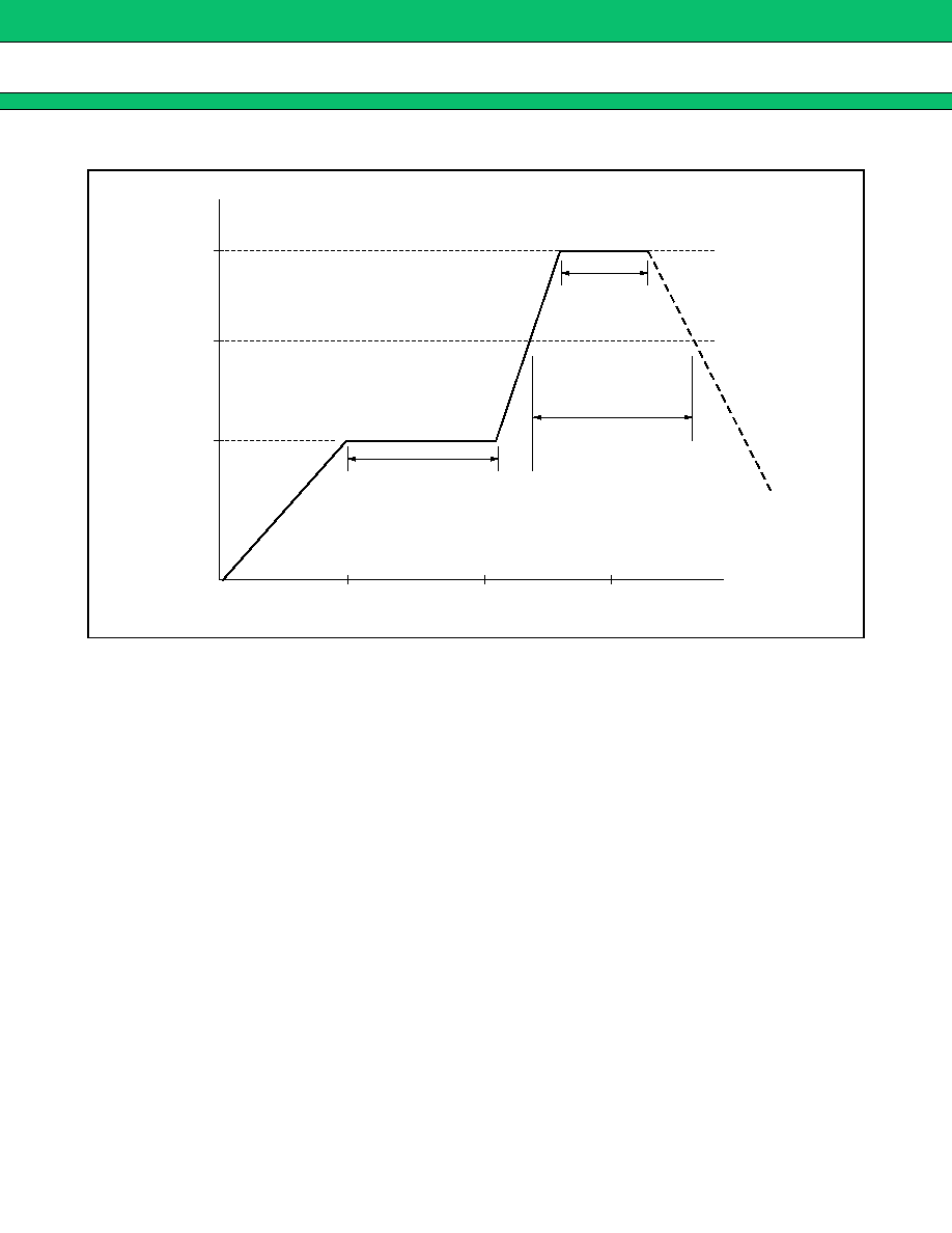
RECOMMENDED REFLOW PROFILE
s
s
s
s
NOTE
Mass-produced product order is accepted by a unit of 1000.
240
210
150
Pre-Heating
10 s
60 s
60
90 s
Time (s)
Temperature (
∞
C)
Heating rate
1 to 4
∞
C/s
Air cooling

G5/G6 Series
FUJITSU MEDIA DEVICES LIMITED
For further information please contact:
Japan
FUJITSU MEDIA DEVICES LIMITED
International Sales and Marketing Dept.
Sin-Yokohama Square Bldg.,14F,
Shin-Yokohama 2-3-12, Kouhoku-ku,
Yokohama-shi, Kanagawa 222-0033, Japan
Tel: +81-45-471-0061
Fax: +81-45-471-0076
http://www.fujitsu.co.jp/hypertext/fmd/English/index.html
North and South America
FUJITSU MICROELECTRONICS, INC.
3545 North First Street,
San Jose, CA 95134-1804, U.S.A.
Tel: +1-408-922-9000
Fax: +1-408-922-9179
Customer Response Center
Mon. - Fri.: 7 am - 5 pm (PST)
Tel: +1-800-866-8608
Fax: +1-408-922-9179
http://www.fujitsumicro.com/
Europe
FUJITSU MICROELECTRONICS EUROPE GmbH
Am Siebenstein 6-10,
D-63303 Dreieich-Buchschlag,
Germany
Tel: +49-6103-690-0
Fax: +49-6103-690-122
http://www.fujitsu-fme.com/
Asia Pacific
FUJITSU MICROELECTRONICS ASIA PTE. LTD.
#05-08, 151 Lorong Chuan,
New Tech Park,
Singapore 556741
Tel: +65-281-0770
Fax: +65-281-0220
http://www.fmap.com.sg/
F0012
©
FUJITSU LIMITED Printed in Japan
All Rights Reserved.
The contents of this document are subject to change without notice.
Customers are advised to consult with FUJITSU sales
representatives before ordering.
The information and circuit diagrams in this document are
presented as examples of semiconductor device applications, and
are not intended to be incorporated in devices for actual use. Also,
FUJITSU is unable to assume responsibility for infringement of
any patent rights or other rights of third parties arising from the use
of this information or circuit diagrams.
The contents of this document may not be reproduced or copied
without the permission of FUJITSU LIMITED.
FUJITSU semiconductor devices are intended for use in standard
applications (computers, office automation and other office
equipments, industrial, communications, and measurement
equipments, personal or household devices, etc.).
CAUTION:
Customers considering the use of our products in special
applications where failure or abnormal operation may directly
affect human lives or cause physical injury or property damage, or
where extremely high levels of reliability are demanded (such as
aerospace systems, atomic energy controls, sea floor repeaters,
vehicle operating controls, medical devices for life support, etc.)
are requested to consult with FUJITSU sales representatives before
such use. The company will not be responsible for damages arising
from such use without prior approval.
Any semiconductor devices have inherently a certain rate of failure.
You must protect against injury, damage or loss from such failures
by incorporating safety design measures into your facility and
equipment such as redundancy, fire protection, and prevention of
over-current levels and other abnormal operating conditions.
If any products described in this document represent goods or
technologies subject to certain restrictions on export under the
Foreign Exchange and Foreign Trade Control Law of Japan, the
prior authorization by Japanese government should be required for
export of those products from Japan.