 | –≠–ª–µ–∫—Ç—Ä–æ–Ω–Ω—ã–π –∫–æ–º–ø–æ–Ω–µ–Ω—Ç: FBR12HD04 | –°–∫–∞—á–∞—Ç—å:  PDF PDF  ZIP ZIP |
(a)
Series Name
FBR12 : FBR12 Series
(b)
Enclosure & Coil Power
N
: Standard (plastic sealed type)
W
: High dielectric strength type (plastic sealed type)
H
: High sensitivity type
(c)
Coil Type
D
: DC coil
(d)
Nominal Voltage
Refer to the COIL DATA CHART
(e)
Contact Material
Nil
: Gold-overlay silver-nickel
≠P
: Gold-overlay silver-palladium
(f)
Custom Designation
To be assigned custom specification
(g)
CSA Standard
≠CSA
: UL114 + CSA recognized
≠CSA
: UL1950 + CSA (under application)
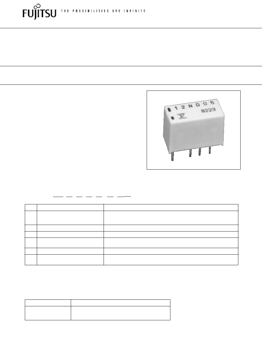
Note: The designation name is stamped on the top of the relay case as follows:
(Example) Designation ordered: FBR12ND05
Stamp: 12ND05
s
FEATURES
q
Super miniature size: 0.2 inch
◊
0.1 inch grid, 12 pin DIP
Up to 50% less volume and board area than previous
generation telecom relay.
q
Slim type for high density mounting
q
Conforms to Bellcore TR-NWT-001089 and FCC Part 68
requirements
q
UL recognized and CSA certified
q
Low power consumption
q
Conforms to IEC 950 (W type only)
≠ 2.5 mm clearance and creepage between coil and contacts
≠5000 V surge strength between coil and contacts (2x10
µ
s
surge wave)
≠2000 Vrms dielectric strength between coil and contacts
≠UL 1950 and IEC950 (approval in process)
FBR12 N
D
12
≠P
≠**
(≠CSA)
[Example]
(a)
(b)
(c)
(d)
(e)
(f )
(g)
FBR12 SERIES
MINIATURE RELAY
2 POLES--1 to 2 A (FOR SIGNAL SWITCHING)
s
ORDERING INFORMATION
1
s
SAFETY STANDARD AND FILE NUMBERS
Nominal coil voltage
Contact rating
0.5 A 125 VDC resistive
3 to 24 VDC
2 A 30 VDC resistive
0.3 A 110 VAC
resistive
UL508, 1950, 114 (File No. E63615)
C22.2 No. 0, No. 14 (File No. LR40304 or LR64026)
NOT FOR NEW
DESIGNS
FBR12ND/HD TO
BE DISCONTINIED -
EXCEPT
FBR12WD
2
FBR12 SERIES
NOT FOR NEW
DESIGNS
FBR12ND/HD TO
BE DISCONTINIED -
EXCEPT
FBR12WD
Life
Mechanical
1
◊
10
8
operations minimum
Electrical DC
2
◊
10
5
operations minimum 5
◊
10
5
operations minimum
(at contact rating)
AC
1
◊
10
5
operations minimum
200
◊
10
3
operations minimum
Other
Vibration Misoperation
10 to 55 Hz (double amplitude of 3.3 mm)
Resistance
Endurance
10 to 55 Hz (double amplitude of 5.0 mm)
Shock
Misoperation
500 m/s
2
(11
±
1
ms)
Resistance
Endurance
1,000 m/s
2
( 6
±
1
ms)
Weight
Approx. 1.5 g Approx. 1.9 g Approx. 1.5 g Approx. 1.9 g
s
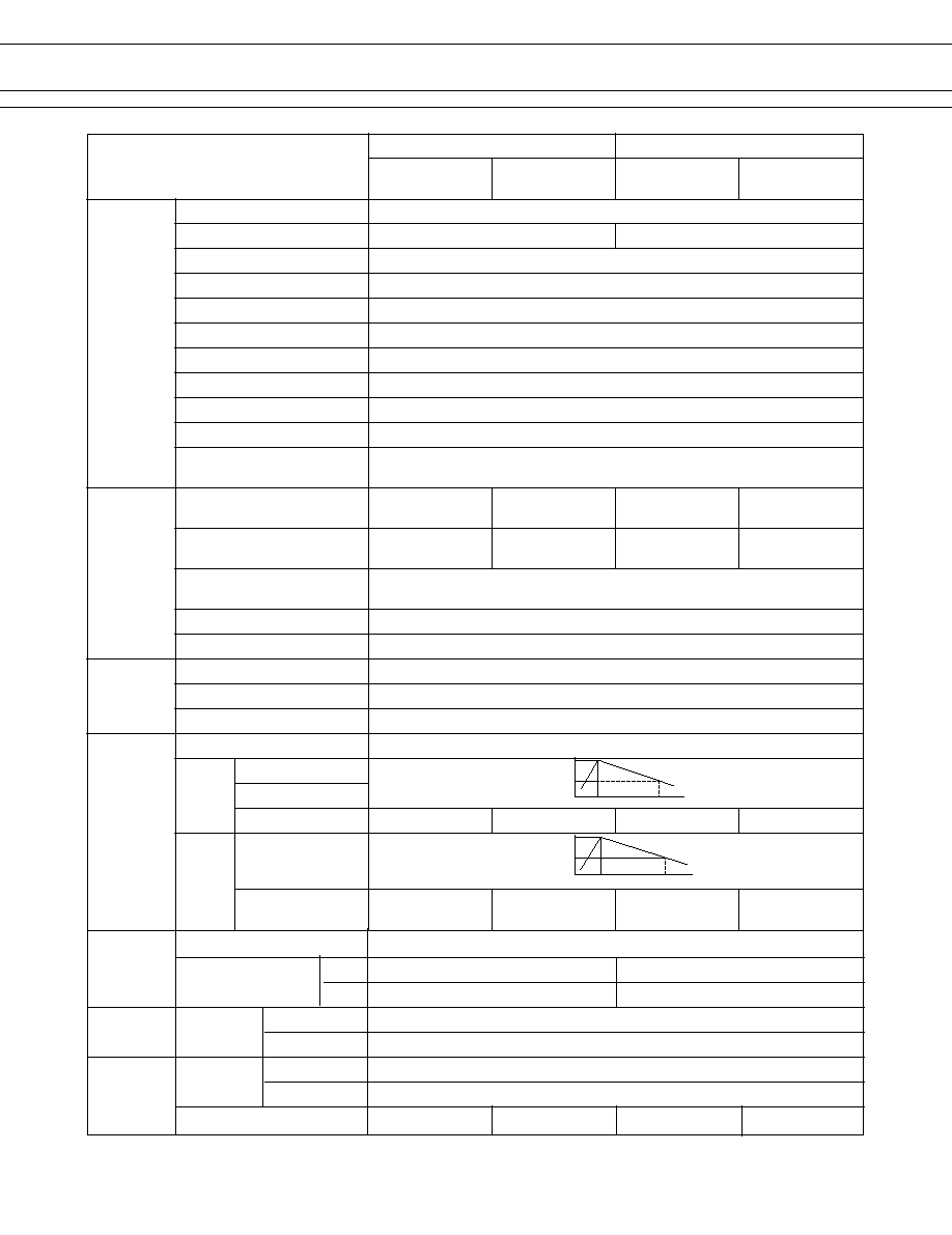
SPECIFICATIONS
Item
Standard (Gold-overlay silver-nickel)
-P type (Gold-overlay silver-palladium)
Standard
High dielectric
Standard
High dielectric
strength type
strength type
Contact
Arrangement
2 form C (DPDT)
Material
Gold-overlay silver-nickel Gold-overlay silver-palladium
Style
Bifurcated
Resistance (initial)
Maximum 100 m
(at 0.1 A 6 VDC)
Rating (resistive)
0.5 A 125 VAC or 1 A 30 VDC
Maximum Carrying Current
2 A (at 20
∞
C)
Maximum Switching Power
62.5 VA or 60 W
Max. Switching Voltage*
1
250 VAC or 220 VDC
Maximum Switching Current
2 A
Minimum Switching Load*
2
10
µ
A 10 VDC (reference)
Capacitance
Approximately 1.0 pF (between open contacts, adjacent contacts )
(at 10 kHz) Approximately1.0 pF (between coil and contacts)
Coil
Nominal power (at 20
∞
C)
Approximately Approximately Approximately Approximately
0.14 to 0.2 W 0.23 to 0.25 W 0.14 to 0.2 W 0.23 to 0.25 W
Operate power (at 20
∞
C)
Approximately Approximately Approximately Approximately
0.08 to 0.112 W 0.13 to 0.14 W 0.08 to 0.112 W 0.13 to 0.14 W
Thermal Resistance at
Approximately 115
∞
C/W
Continuous Thermal Load
Operating Temperature
≠40
∞
C to +85
∞
C (no frost) (refer to the CHARACTERISTIC DATA)
Operating Humidity
45 to 85%RH
Time Value
Operate (at nominal voltage)
Maximum 4 msec.
Release (at nominal voltage)
Maximum 4 msec.
Max. Switching Frequency
Mechanical 3 Hz or electrical 0.5 Hz (at contact rating)
Insulation
Resistance (initial)
Minimum 1000 M
(at 500 VDC)
Dielectric between open contacts
1,000 VAC
Strength
adjacent contacts
1 minimum
between coil and contacts
1,500 VAC 1 min. 2,000 VAC 1 min. 1,500 VAC 1 min. 2,000 VAC 1 min.
Surge between open
1,500 V
Strength contacts,
10
◊
700
µ
s
adjacent contacts
between coil and contacts
2,500 V 5,000 V 2,500 V 5,000 V
2
◊
10
µ
s 2
◊
10
µ
s 2
◊
10
µ
s 2
◊
10
µ
s
1,500
750
10
700
2,500
1,250
2
10
*
1
If the switching voltage exceeds the rated contact voltage, reduce the current. The current values vary according to the
type of load.
*
2
Values when switching a resistive load at normal room temperature and humidity and in a clean environment.
The minimum switching load varies with the switching frequency and operation environment.

3
FBR12 SERIES
NOT FOR NEW
DESIGNS
FBR12ND/HD TO
BE DISCONTINIED -
EXCEPT
FBR12WD
Item
High Sensitive Type
Standard (Gold-overlay silver-nickel) -P type (Gold-overlay silver-palladium)
Contact
Arrangement
2 form C (DPDT)
Material
Gold-overlay silver-nickel
Gold-overlay silver-palladium
Style
Bifurcated
Resistance (initial)
Maximum 100 m
(at 0.1 A 6 VDC)
Rating (resistive)
0.3 A 125 VAC or 1 A 30 VDC
Maximum Carrying Current
2 A (at 20
∞
C)
Maximum Switching Power
62.5 VA or 30 W
Max. Switching Voltage*
1
250 VAC or 220 VDC
Maximum Switching Current
2 A
Minimum Switching Load*
2
10m VDC - 10
µ
A
Capacitance
Approximately 1.0 pF (between open contacts, adjacent contacts )
(at 10 kHz) Approximately1.0 pF (between coil and contacts)
Coil
Nominal power (at 20
∞
C)
Approximately 50mW
Operate power (at 20
∞
C)
Approximately 40m W
Operating Temperature
≠40
∞
C to +70
∞
C (no frost) (refer to the CHARACTERISTIC DATA)
Operating Humidity
45 to 85%RH
Time Value
Operate (at nominal voltage)
Maximum 5 msec.
Release (at nominal voltage)
Maximum 5 msec.
Insulation
Resistance (initial)
Minimum 1000 M
(at 500 VDC)
Dielectric between open contacts
750 VAC
Strength
adjacent contacts
1 minute
between coil and contacts
1,500 VAC 1 minutes
Surge between open
1,500 V
Strength contacts,
10
◊
700
µ
s
adjacent contacts
between coil and contacts
2,500 V
2
◊
10
µ
s
Life
Mechanical
1 x 10
8
operations minimum
Electrical DC
2
◊
10
5
operations minimum 5
◊
10
5
operations minimum
(at contact rating)
AC
1
◊
10
5
operations minimum
200
◊
10
3
operations minimum
Other
Vibration Misoperation
10 to 55 Hz (double amplitude of 3.3` mm)
Resistance
Endurance
10 to 55 Hz (double amplitude of 5.0 mm)
Shock
Misoperation
500 m/s
2
(11
±
1
ms)
Resistance
Endurance
1,000 m/s
2
( 6
±
1
ms)
Weight
Approx. 1.9 g
s
SPECIFICATIONS
*
1
If the switching voltage exceeds the rated contact voltage, reduce the current. The current values vary according to the
type of load.
*
2
Values when switching a resistive load at normal room temperature and humidity and in a clean environment.
The minimum switching load varies with the switching frequency and operation environment.
4
FBR12 SERIES
NOT FOR NEW
DESIGNS
FBR12ND/HD TO
BE DISCONTINIED -
EXCEPT
FBR12WD
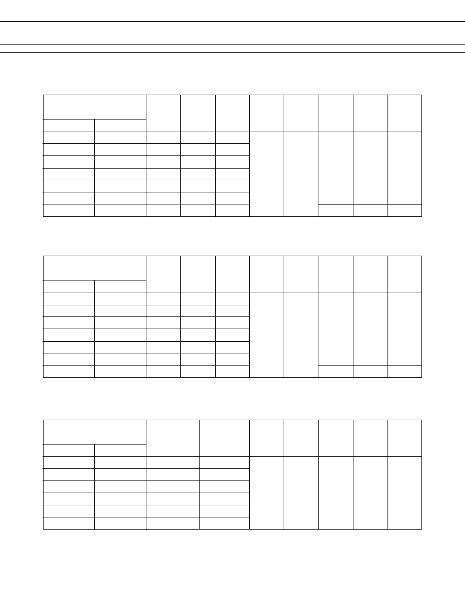
MODEL
Nominal
Nominal
Coil
current
Must
Must
Nominal
Operate
Coil
resistance (at nominal
operate
operate
temperature
voltage
(
±
10%)
voltage)
voltage*
1
voltage*
1
power
power
rise
Standard
-P type
approx.
FBR12ND03
FBR12ND03-P
3 VDC
64.3
46 mA
FBR12ND04
FBR12ND04-P
4.5 VDC
145
31 mA
FBR12ND05
FBR12ND05-P
5 VDC
178
28 mA
75% max. 10% min.
Approx.
Approx.
Approx.
of nominal of nominal
0.14 W
0.08 W
20 deg
FBR12ND06
FBR12ND06-P
6 VDC
257
23 mA
(at nominal
Max.
voltage
voltage
voltage)
Max.
(at nominal
FBR12ND09
FBR12ND09-P
9 VDC
579
15 mA
voltage)
FBR12ND12
FBR12ND12-P
12 VDC
1,028
11 mA
FBR12ND24
FBR12ND24-P
24 VDC
2,880
8 mA
0.2 W
0.112 W
30 deg
s
COIL DATA CHART
*1: Specified values are subject to pulse wave voltage.
Note: All values in the table are measured at 20
∞
C.
MODEL
Nominal
Nominal
Coil
current
Must
Must
Nominal
Operate
Coil
resistance (at nominal
operate
release
temperature
voltage
(
±
10%)
voltage)
voltage*
1
voltage*
1
power
power
rise
Standard
-P type
approx.
FBR12WD03
FBR12WD03-P 3 VDC
39
77 mA
FBR12WD04
FBR12WD04-P 4.5 VDC
88
51 mA
FBR12WD05
FBR12WD05-P 5 VDC
108
46 mA
75% max. 10% min.
Approx.
Approx.
Approx.
of nominal of nominal
0.23 W
0.13 W
30 deg
FBR12WD06
FBR12WD06-P 6 VDC
156
38 mA
(at nominal
(at nominal
voltage
voltage
voltage)
Max.
voltage)
FBR12WD09
FBR12WD09-P 9 VDC
352
25 mA
FBR12WD12
FBR12WD12-P 12 VDC
626
19 mA
FBR12WD24
FBR12WD24-P 24 VDC
2,304
10 mA
0.25 W
0.14 W
33 deg
*1: Specified values are subject to pulse wave voltage.
Note: All values in the table are measured at 20
∞
C.
1.STANDARD
2.HIGH DIELECTRIC STRENGTH
MODEL
Nominal Coil
Must
Must
Nominal
Operate
Coil
resistance
operate
release
temperature
voltage (
±
10%)
voltage*
1
voltage*
1
power
power
rise
Standard
-P type
FBR12HD03
FBR12HD03-P 3 VDC 180
FBR12HD04
FBR12HD04-P 4.5 VDC 405
FBR12HD05
FBR12HD05-P 5 VDC 500
80% max. 10% min.
Approx.
Approx.
Approx.
of nominal of nominal
0.05 W
0.04 W
4 deg
FBR12HD06
FBR12HD06-P 6 VDC 720
(at nominal
(at nominal
voltage
voltage
voltage)
Max.
voltage)
FBR12HD09
FBR12HD09-P 9 VDC 1,620
FBR12HD12
FBR12HD12-P 12 VDC 2,880
*1: Specified values are subject to pulse wave voltage.
Note: All values in the table are measured at 20
∞
C.
3. HIGH SENSITIVITY TYPE
5
FBR12 SERIES
NOT FOR NEW
DESIGNS
FBR12ND/HD TO
BE DISCONTINIED -
EXCEPT
FBR12WD
s
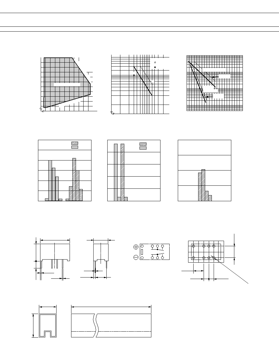
DIMENSIONS
Unit: mm
s
REFERENCE DATA
s
CHARACTERISTIC DATA
Life curve
500
Contact load current (A)
50
5
10
1
100
(
◊
10
4
)
Service life (operations)
0.5
1.0
1.5
2.0
Maximum switching capacity
Contact load voltage (V)
0.1
10
20
125
200
30
50
0.2
0.3
0.5
1.0
2.0
Range of operation temperature and voltage
Operating temperature (∞C)
≠10 0 10 20 30 40 50 60 70 80
70
80
90
100
110
120
130
140
150
160
AC resistive load
( AC contact rating)
DC resistive load
( DC contact rating)
Operating voltage range
Must operate voltage
Maximum allowable coil voltage
(DATA) assumes that
the maximum allow-
able temperature of
E type insulation
coil is 115∞C
Contact load current (A)
Nominal voltage multiplying factor (%)
125 V AC
resistive load
30 V DC resistive load
(≠P)TYPE
(≠P)TYPE
q
Dimensions
q
Schematics
(BOTTOM VIEW)
q
PC board mounting hole layout
(BOTTOM VIEW)
q
Tube carrier
14.6
+0.4
0.50
(0.95)
9.7
+0.3
3.2
7.2
+0.3
0.25
(1.06)
5.08
1
12
3
10
4
9
5
8
5.08
2.54
5.08
2.54
8≠¯1.00
10.6 Max.
30 pcs/Tube
15.6 Max.
500
±
2
V
SHOW ONE OUT
OF THBSB 3 DIMENSIONS (See NA)
Operate
Release
Distribution of operate and release voltage
Rated coil voltage multiplying factor (%)
60
50
40
20
30
10
0
10
20
30
40
50
60
70
80
0
Distribution (%)
Operate
Release
Distribution of operate and release time
Time (ms)
100
80
60
20
40
0
1
2
3
4
5
6
7
8
0
Contact resistance (m
)
Distribution of contact resistance
80
60
40
20
0
10
20
30
40
50
60
70
80
0
Distribution (%)
Distribution (%)

6
FBR12 SERIES
NOT FOR NEW
DESIGNS
FBR12ND/HD TO
BE DISCONTINIED -
EXCEPT
FBR12WD
© 2001 Fujitsu Components America, Inc. All company and product names are trademarks or registered trademarks
of their respective owners. Rev. 09/2001
Japan
Fujitsu Component Limited
Gotanda-Chuo Building
3-5, Higashigotanda 2-chome, Shinagawa-ku
Tokyo 141, Japan
Tel: (81-3) 5449-7010
Fax: (81-3) 5449-2626
Email: promothq@ft.ed.fujitsu.com
Web: www.fcl.fujitsu.com
North and South America
Fujitsu Components America, Inc.
250 E. Caribbean Drive
Sunnyvale, CA 94089 U.S.A.
Tel: (1-408) 745-4900
Fax: (1-408) 745-4970
Email: marcom@fcai.fujitsu.com
Web: www.fcai.fujitsu.com
Europe
Fujitsu Components Europe B.V.
Diamantlaan 25
2132 WV Hoofddorp
Netherlands
Tel: (31-23) 5560910
Fax: (31-23) 5560950
Email: info.marketing@fceu.fujitsu.com
Web: www.fceu.fujitsu.com
Asia Pacific
Fujitsu Components Asia Ltd.
102E Pasir Panjang Road
#04-01 Citilink Warehouse Complex
Singapore 118529
Tel: (65) 375-8560
Fax: (65) 273-3021
Email: fcal@fcal.fujitsu.com
www.fcal.fujitsu.com
Fujitsu Components
International
Headquarter
Offices