 | –≠–ª–µ–∫—Ç—Ä–æ–Ω–Ω—ã–π –∫–æ–º–ø–æ–Ω–µ–Ω—Ç: FBR161 | –°–∫–∞—á–∞—Ç—å:  PDF PDF  ZIP ZIP |
s
FEATURES
q
Suitable for automotive applications such as motor load
controls, door locks, power windows, wipers, etc.
q
Variety of contact materials covering wide current switching
in range of 15 A to 25 A (at 14 VDC)
q
FBR166 series with high conductive spring and improved
break performance is also available
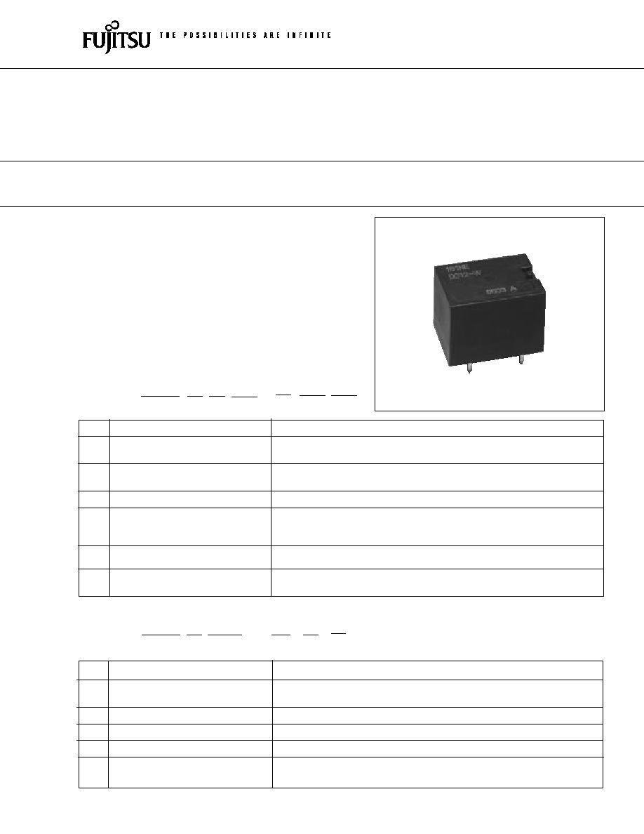
FBR161,166 Series
POWER RELAY
1 POLE--15 to 25 A
(FOR AUTOMOTIVE APPLICATIONS)
(a)
Series Name
FBR166: 1 form C FBR166 Series
(b)
Enclosure
S
: Flux free type
N
: Plastic sealed type
(c)
Nominal Voltage
CD009 : 9 VDC (example)
(d)
Contact Material
WB
: Silver-tin oxide indium (25 A maximum)
(e)
Custom Designation
Custom specification to be assigned
(f)
Package Style
Nil
: Standard tray
-S : Tube carrier
FBR166
S
CD009 ≠
WB ** ≠ **
[Example]
(a)
(b)
(c)
(d) (e) (f)
q
FBR166 Series
q
FBR161 Series
s
ORDERING INFORMATION
FBR161
S
E
D012 ≠ W ** **
[Example]
(a)
(b) (c)
(d)
(e) (f ) (g)
(a)
Series Name
FBR161: 1 form C FBR161 Series
(b)
Enclosure
S
: Flux free type
N
: Plastic sealed type
(c)
Coil Type
E
: Nominal power 0.36 to 0.38 W
C
: Nominal power 0.45 to 0.5 W
(d)
Nominal Voltage
D012
: 12 VDC (example)
C
: Silver copper (15 A maximum)
(e)
Contact Material
W
: Silver-tin oxide indium (20 A maximum)
WB
: Silver-tin oxide indium (25 A maximum)
( f )
Custom Designation
Custom specification to be assigned
(g)
Package Style
Nil : Standard tray
-S : Tube carrier
1
2
FBR161,166 SERIES
s
SPECIFICATIONS
Item
Specifications
Contact
Arrangement
1 Form C (SPDT)
Material
C : Silver copper (15 A maximum)
W : Silver-tin oxide indium (20 A maximum)
WB : Silver-tin oxide indium (25 A maximum)
Voltage Drop (resistance)
Maximum 100 mV (at 1 A 6 VDC)
Maximum Carrying Current
Contact C and W type: 17 A/1 hour, 5 A (continuously)
Contact WB type : 25 A/1 hour, 10 A (continuously)
(25
∞
C,100% rated coil voltage)
15 A 16 VDC (silver copper: C type)
Maximum Switching Current
20 A 16 VDC (silver-tin oxide indium : W type)
25 A 16 VDC (silver-tin oxide indium: WB type)
Coil
Operating Temperature
≠40
∞
C to + 85
∞
C (no frost) (refer to the CHARACTERISTIC DATA)
Storage Temperature
≠40
∞
C to + 100
∞
C (no frost)
Time Value
Operate (at nominal voltage)
Maximum 10 ms
Release (at nominal voltage)
Maximum 5 ms
Life
Mechanical
1
◊
10
7
operations minimum
FBR160 Series: 1
◊
10
5
operations minimum
Electrical
FBR166 Series: 2
◊
10
5
operations minimum
(14 VDC, maximum switching current, resistive load)
(refer to the CHARACTERISTIC DATA)
Other
Vibration Resistance
10 to 55 Hz (double amplitude of 1.5 mm)
Shock Misoperation
100 m/s
2
(11
±
1
ms)
Resistance Endurance
1,000 m/s
2
(11
±
1
ms)
Weight
Approximately 11 g
s
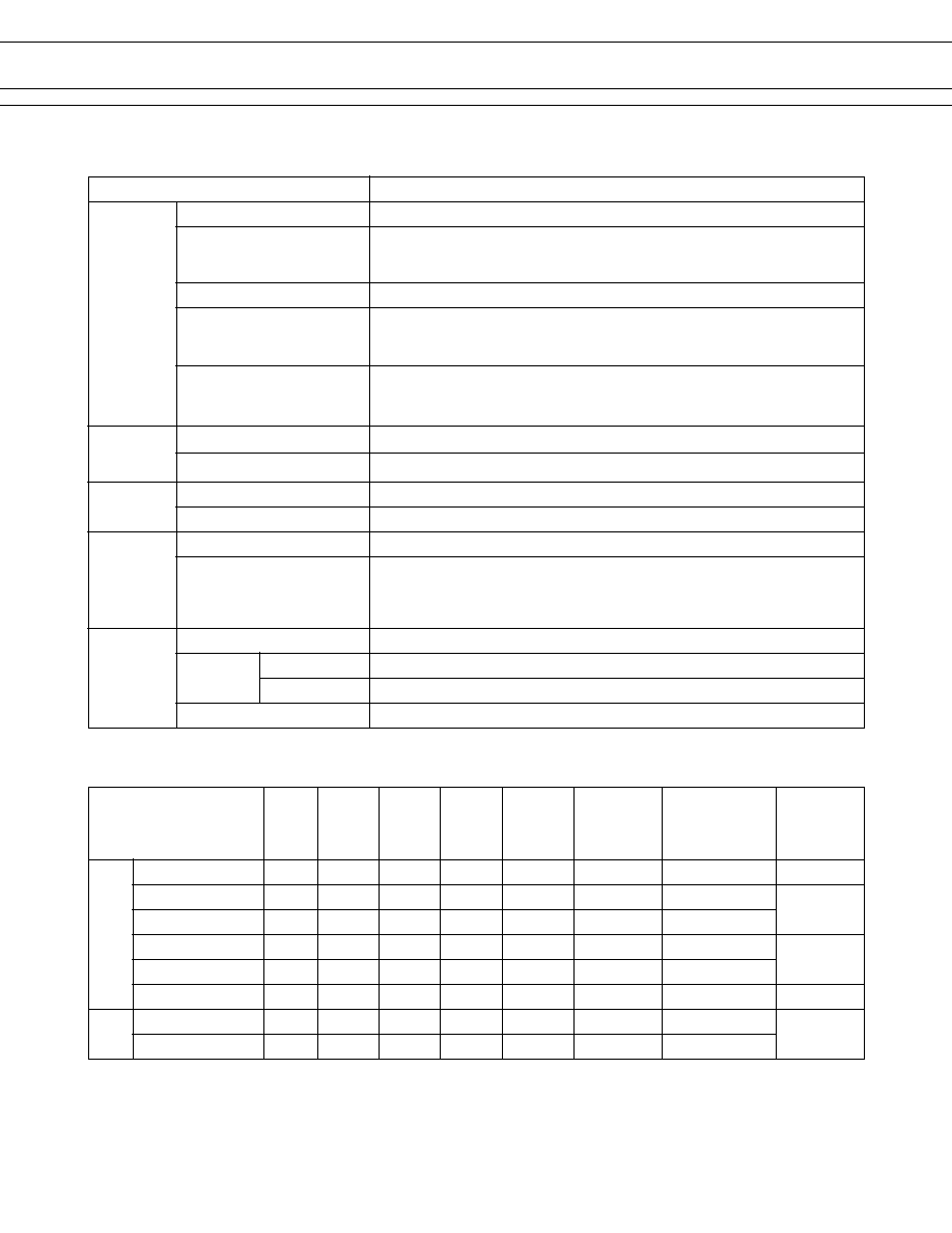
COIL RATINGS
Coil
Must
Must
Operating
MODEL
Nominal resistance
operate
operate
voltage
Nominal
Contact
Thermal
voltage
voltage
voltage
voltage
(reference)
power
material
resistance
±
10%
(+20
∞
C)
(+80
∞
C)
FBR161 FBR161S (N) ED009-W32
9 VDC*
210
6.0 V
7.4 V
6.0 V to 14.0 V Approx. 380 mW
Silver tin indium oxide
84
∞
C/W
Series
FBR161S (N) ED009-W12
9 VDC*
225
6.5 V
8.0 V
6.5 V to 14.0 V Approx. 360 mW
Silver tin indium oxide
83
∞
C/W
FBR161S (N) ED009-WB38 9 VDC*
225
6.3 V
8.0 V
6.5 V to 16.0 V Approx. 360 mW
Silver tin indium oxide
FBR161S (N) CD012-C36
12 VDC
320
7.3 V
9.0 V
7.3 V to 15.5 V Approx. 450 mW
Silver copper
78
∞
C/W
FBR161S (N) CD012-W36
12 VDC
320
7.3 V
9.0 V
7.3 V to 15.0 V Approx. 450 mW
Silver tin indium oxide
FBR161S (N) CD012-W31
12 VDC
290
7.3 V
9.0 V
7.3 V to 15.5 V Approx. 500 mW
Silver tin indium oxide
76
∞
C/W
FBR166 FBR166S (N) CD009-WB
9 VDC*
120
6.3 V
7.8 V
6.3 V to 14.0 V Approx. 670 mW
Silver tin indium oxide
Series
67
∞
C/W
FBR166S (N) CD012-WB
12 VDC
210
7.3 V
9.0 V
7.3 V to 14.0 V Approx. 680 mW
Silver tin indium oxide
* For typical 12 VDC automotive applications.
3
FBR161,166 SERIES
s
CHARACTERISTIC DATA
s
REFERENCE DATA
1. SERVICE LIFE WITH ACTUAL MOTOR LOAD TEST (example)
∑ Wiper motor (free, 16 VDC inrush 20 A, break 2 A) : more than 3
◊
10
5
operations
(FBR160-W, silver tin oxide alloy)
∑ Wiper motor (free, 14 VDC inrush 25 A, break 5 A) : more than 5
◊
10
5
operations
(FBR160-WB, silver tin oxide alloy)
∑ Door lock motor (stall, 14 VDC inrush -25 A) : more than 1
◊
10
5
operations
(FBR160-W, silver tin oxide alloy)
∑ Door lock motor (stall, 14 VDC inrush -25 A) : more than 2
◊
10
5
operations
(FBR166)
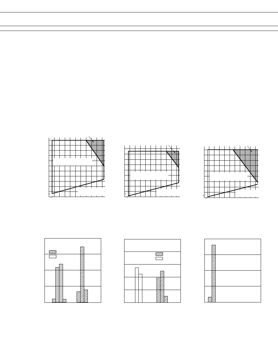
2. OPERATING COIL VOLTAGE (example)
[FBR161S(N)ED009-W32,
approximately 380 mW type]
60
70
80
90
100
110
120
130
140
150
160
≠10 0 10 20 30 40 50 60 70 80
Ratio of operating
voltage to rated coil voltage
Operating temperature (∞C)
Intermittent coil operation
is required.
Continuously applicable coil
voltage range
Pick-up voltage
(minimum operating voltage)
≠10 0 10 20 30 40 50 60 70 80
Intermitted coil operation is
required.
[FBR166S (N) CD012-WB,
approximately 680 mW type]
Operating temperature (∞C)
60
70
80
90
100
110
120
130
140
Continuously applicable coil
voltage range
Ratio of operating
voltage to rated coil voltage
Pick-up voltage
(Minimum operating voltage)
80
60
40
20
0
10 20 30 40 50 60 70 80
0
Distribution (%)
FBR161
n = 100
Operate
Release
Distribution of operate and release voltage
Nominal voltage multiplying factor (%)
1000
80
60
20
40
0
1
2
3
4
5
6
7
8
0
Distribution (%)
FBR161
n = 100
Operate
Release
Distribution of operate and release time
Time (ms)
100
75
50
25
0
10 20 30 40 50 60 70 80
0
Distribution (%)
Contact resistance (m
)
Distribution of contact resistance
FBR161
n = 100
≠10 0 10 20 30 40 50 60 70 80
Intermittent coil operation
is required.
[FBR161SCD012-W36,
Approximately 450 mW type]
Operating temperature (∞C)
60
70
80
90
100
110
120
130
140
Continuously applicable coil
voltage range
Ratio of operating
voltage to rated coil voltage
Pick-up voltage
(minimum operating voltage)
4
FBR161,166 SERIES
s
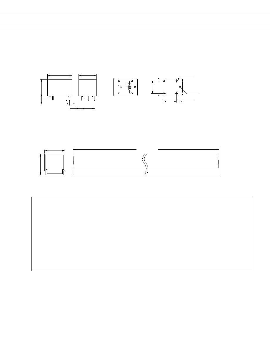
DIMENSIONS
Unit: mm
(2.3)
16.2
+0.3
21.7
+0.5
16.2
+0.3
0.4
3.5
ÿ 12.0
±
0.1
12.2
±
0.1
2.1
±
0.1
ÿ1.4
±
0.1
4≠ÿ 1.3
±
0.1
Note : For 1 form A type, terminal No.4 is removed.
4
3
5
2
1
q
Dimensions
q
Tube carrier
q
PC board mounting hole layout
q
Schematic
25.8 max.
22.3 max.
25 pieces/tube
601 maximum
(BOTTOM VIEW)
(BOTTOM VIEW)
12.2
2.1
12.0
(2.1)
6.0
22.5 Max.
(2.3)
(2.25)
12.0
4-ÿ 1.3
±
0.1
12.0
±
0.1
ÿ 1.4
±
0.1
12.2
±
0.1
2.1
±
0.1
16.5 Max.
3.5
16.5 Max.
q
Schematic
(BOTTOM VIEW)
q
Dimensions
4
5
3
2
1
q
PC board mounting hole layout
(BOTTOM VIEW)
© 2003 Fujitsu Components America, Inc. All company and product names are trademarks or registered trademarks
of their respective owners. Rev. 02/18/2003
Japan
Fujitsu Component Limited
Gotanda-Chuo Building
3-5, Higashigotanda 2-chome, Shinagawa-ku
Tokyo 141, Japan
Tel: (81-3) 5449-7010
Fax: (81-3) 5449-2626
Email: promothq@ft.ed.fujitsu.com
Web: www.fcl.fujitsu.com
North and South America
Fujitsu Components America, Inc.
250 E. Caribbean Drive
Sunnyvale, CA 94089 U.S.A.
Tel: (1-408) 745-4900
Fax: (1-408) 745-4970
Email: marcom@fcai.fujitsu.com
Web: www.fcai.fujitsu.com
Europe
Fujitsu Components Europe B.V.
Diamantlaan 25
2132 WV Hoofddorp
Netherlands
Tel: (31-23) 5560910
Fax: (31-23) 5560950
Email: info@fceu.fujitsu.com
Web: www.fceu.fujitsu.com
Asia Pacific
Fujitsu Components Asia Ltd.
102E Pasir Panjang Road
#04-01 Citilink Warehouse Complex
Singapore 118529
Tel: (65) 6375-8560
Fax: (65) 6273-3021
Email: fcal@fcal.fujitsu.com
www.fcal.fujitsu.com
Fujitsu Components
International
Headquarter
Offices