
s
ORDERING INFORMATION
FBR16
1
S
E
D
012
UH
≠CSA
≠*** ≠S
[Example]
(a)
(b)
(c)
(d)
(e)
(f )
(g)
(h)
(i)
( j)
s
FEATURES
q
Compact with high power (3 A to 10 A)
q
6 types of contact materials available for home electronics
and automotive applications
q
Design conforms to the following safety standards
UL114 No. E63615
UL508 No. E63614
CSA
No. LR64026
Japan Electric Appliance Control Law (150≠300 V)
q
For automatic assembly
Tube packaging suitable for automatic insertion
equipment is available
(a)
Series Name
FBR16: FBR160 Series
(b)
Contact Arrangement
1
: 1 form C (SPDT)
3
: 1 form A (SPST-NO)
(c)
Enclosure
S
: Flux free
N
: Plastic sealed
(d)
Coil Rating
E
: Nominal power 0.36 W type
C
: Nominal power 0.5 W type (refer to the SPECIFICATIONS)
(e)
Coil
D
: DC Coil
( f )
Nominal Voltage
(Example) 012: 12 VDC coil
024: 24 VDC coil (refer to the COIL DATA CHART)
(g)
UL Standard and Contact Material
UL 114
UL508
Material / Rating
recognized
recognized
U
R
Silver (3A)
UK
RK
Silver-cadmium oxide (3 A)
UH
RH
Silver-cadmium oxide (5 A)
UW
RW
Silver tin oxide alloy (5 A)
UHB
RHB
Silver-cadmium oxide (AC 10 A)
UWB
RWB
Silver tin oxide alloy (DC 10 A
(Continued)
FBR160 SERIES
POWER RELAY
1 POLE-- 3, 5, 10 A
1

2
FBR160 SERIES
(h)
CSA Standard
No designation: standard
-CSA: CSA recognized (g) specifies UL 114 or UL 508
( i )
Custom Designation
Suffix number for custom design
( j )
Package Style
Nil
: Standard tray
-S
: Tube carrier
Note: The designation name is stamped on the top of the relay case as follows:
(Example) Designation ordered: FBR161NED012-H
Stamp: 161NED012-H
s
SAFETY STANDARD AND FILE NUMBERS
UL 114 (File No. E63615)
UL 508 (File No. E63614)
C22.2, No. 14 (File No. LR40304, LR61320 or LR64026)
5 to 24 VDC
Nominal voltage
Type (contact material)
Contact rating
Silver (no designation)
3 A
120 VAC/ 30 VDC resistive
Silver-cadmium oxide (-K)
1/10 HP
120 VAC
Silver-cadmium oxide(-H)
5 A
120 VAC/30 VDC resistive
1/6 HP
120 VAC
Silver tin oxide alloy (-W)
Silver tin oxide alloy (-WB)
10 A (N.O.) 7 A (N.C.) 120 VAC/250 VAC resistive
10 A
30 VDC resistive
Silver-cadmium oxide (-HB)
1/8 HP
120 VAC/250 VAC
3
FBR160 SERIES
s
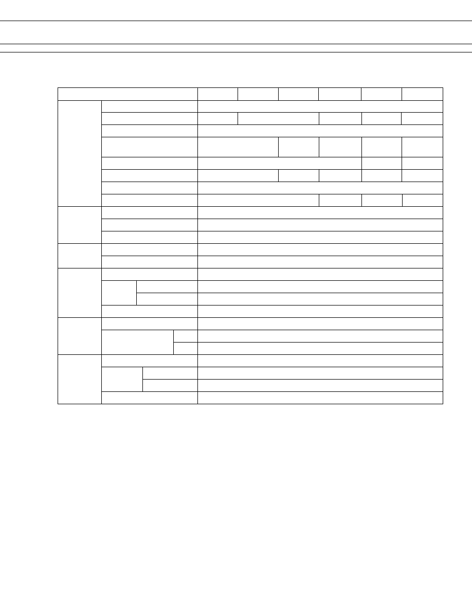
SPECIFICATIONS
Item
--
-K
-H
-W
-HB
-WB
Contact
Arrangement and Style
1 form C or 1 form A, single contact
Material
Silver
Silver-cadmium oxide
Silver tin oxide alloy Silver-cadmium oxide Silver tin oxide alloy
Resistance (initial)
Maximum 100 m
(silver contact at 0.5 A 6 VDC/other contacts at 1 A 6 VDC)
Ratings (resistive load)
3 A 120 VAC
5 A 120 VAC 5 A 28 VDC
10 A 120 VAC (N.O.) 10 A 28 VDC
3 A 28 VDC
5 A 28 VAC
7 A 120 VAC (N.C.)
Maximum Carrying Current
5 A
10 A
10 A
Maximum Switching Power
360 VA or 84 W
Max. Switching Voltage*
1
250 VAC or 125 VDC
Minimum Switching Load*
2
0.3 W (30 mA 5 V)
0.3 W (50 mA 5 V)
0.5 W (100 mA 5 V) 0.5 W (100 mA 5 V)
Coil
Nominal Power
Approx. 0.36 W (E coil type)/0.5 W (C coil type) (at 20
∞
C)
Operating Temperature
≠30
∞
C to +80
∞
C (no frost) *
3
Operate Humidity
45 to 85% RH
Time Value
Operate (at nominal voltage)
Maximum 10 msec
Release (at nominal voltage)
Maximum 5 msec
Insulation
Resistance (initial)
Minimum 100 M
(at 500 VDC)
Dielectric Between coil and contacts
1,500 VAC 1 minute
Strength
Between open contacts
500 VAC 1 minute
Surge Strength
3,500 V (at 1.2
◊
50
µ
s)
Life
Mechanical 1
◊
10
7
operations minimum
Electrical (refer to
1
◊
10
5
operations minimum (at contact rating)
the REFERENCE
DATA)
1
◊
10
5
operations minimum (at contact rating)
Other
Vibration Resistance
10 to 55 Hz (double amplitude of 1.5mm)
Shock No contact opening
100 m/s
2
(11
±
1
ms)
Resistance
No damage
1,000 m/m
2
(6
±
1
ms)
Weight
Approximately 11 g
*
1
If the switching voltage exceeds the rated contact voltage, reduce the current. The current values vary according to the
type of load.
*
2
Values when switching a resistive load at normal room temperature and humidity, and in a clean environment. The minimum
switching load varies with the switching frequency and operation environment.
*
3
Based on UL Class A coil insulation system.
DC
AC
600 VA or 140 W
140 W
1,200 VA 280 W
4
FBR160 SERIES
80% max. 10% min.
210%
Approx.
Approx.
of
of
of
360 mW
30 deg
nominal
nominal
nominal
(at nominal (at nominal
voltage
voltage
voltage
voltage)
voltage)
s
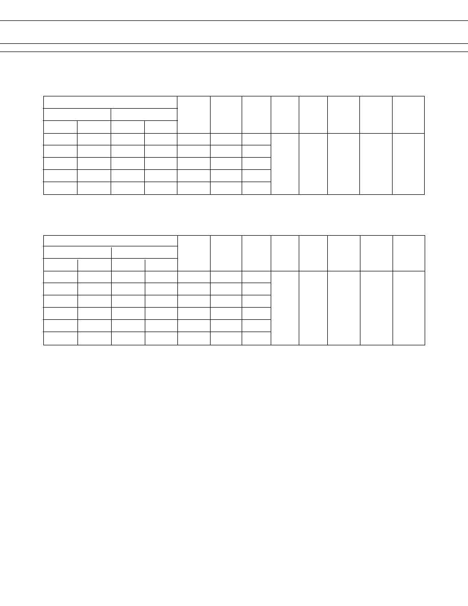
COIL RATINGS
1. E (0.36 WATT COIL TYPE)
MODEL
1 Form C type
1 Form A type
Flux free Plastic sealed Flux free Plastic sealed
FBR161SED005
s
s
FBR161NED005
s
s
FBR163SED005
s
s
FBR163SED005
s
s
5 VDC
70
71 mA
FBR161SED006
s
s
FBR161NED006
s
s
FBR163SED006
s
s
FBR163SED006
s
s
6 VDC
100
60 mA
FBR161SED009
s
s
FBR161NED009
s
s
FBR163SED009
s
s
FBR163SED009
s
s
9 VDC
225
40 mA
FBR161SED012
s
s
FBR161NED012
s
s
FBR163SED012
s
s
FBR163SED012
s
s
12 VDC
400
30 mA
FBR161SED024
s
s
FBR161NED024
s
s
FBR163SED024
s
s
FBR163SED024
s
s
24 VDC
1,600
15 mA
Note: All values in the table are measured at 20
∞
C.
Nominal
Nominal
Coil
current
Must
Must
Maximum
Nominal
Coil
resistance (at nominal operate
release
allowable
power
temperature
voltage
(
±
10%)
voltage)
voltage
voltage
voltage
rise
approx.
75% max. 10% min.
210%
Approx.
Approx.
of
of
of
500 mW
35 deg
nominal
nominal
nominal
(at nominal (at nominal
voltage
voltage
voltage
voltage)
voltage)
2. C (0.5 WATT COIL TYPE)
MODEL
1 Form C type
1 Form A type
Flux free Plastic sealed Flux free Plastic sealed
FBR161SCD005
s
s
FBR161NCD005
s
s
FBR163SCD005
s
s
FBR163SCD005
s
s
5 VDC
50
100 mA
FBR161SCD006
s
s
FBR161NCD006
s
s
FBR163SCD006
s
s
FBR163SCD006
s
s
6 VDC
72
83 mA
FBR161SCD009
s
s
FBR161NCD009
s
s
FBR163SCD009
s
s
FBR163SCD009
s
s
9 VDC
162
56 mA
FBR161SCD012
s
s
FBR161NCD012
s
s
FBR163SCD012
s
s
FBR163SCD012
s
s
12 VDC
288
42 mA
FBR161SCD024
s
s
FBR161NCD024
s
s
FBR163SCD024
s
s
FBR163SCD024
s
s
24 VDC
1,152
21 mA
FBR161SCD048
s
s
FBR161NCD048
s
s
FBR163SCD048
s
s
FBR163SCD048
s
s
48 VDC
4,600
10 mA
Note: All values in the table are measured at 20
∞
C.
Nominal
Nominal
Coil
current
Must
Must
Maximum
Nominal
Coil
resistance (at nominal operate
release
allowable
power
temperature
voltage
(
±
10%)
voltage)
voltage
voltage
voltage
rise
approx.

5
FBR160 SERIES
s
CHARACTERISTIC DATA
Range of operation temperature and voltage
E type [0.36 W type]
Operating temperature (∞C)
Maximum switching capacity (10 A type)
Contact load voltage (V)
0.1
10
20
250
30 50
1.0
120
0.3
0.5
3.0
5.0
10.0
Maximum switching capacity (5 A type)
Contact load voltage (V)
0.1
10
20
250
30 50
1.0
120
0.3
0.5
3.0
5.0
Life curve (5 A type)
Contact load current (A)
30
0
Service life (operations)
5
10
50
100
500
(x10
4
)
0.5
1
2
3
4
5
120 V AC resistive load (≠HB type)
30 V DC resistive load (≠WB type)
120 V AC inductive load (≠HB type)
30 V AC inductive load (≠WB type)
240 V AC resistive load (≠HB type)
240 V AC inductive load (≠HB type)
Life curve
(10 A type, make side (N.O.))
30
0
5
10
50
100
500
(
x
10
4
)
Life curve
(10 A type, breake side (N.C.))
30
0
5
10
50
100
500
(x10
4
)
0.5
2
4
6
8
10
1
0.5
2
4
6
8
10
1
70
80
90
100
110
120
130
140
150
160
≠10 0 10 20 30 40 50 60 70 80
(Data) assumes that
the maximum
allowable tem-
perature of E
type insula-
tion coil is
115∞C
Operating voltage range
Must operate voltage
Nominal voltage multiplying mactor (%)
Maximum allowable coil voltage
Contact load current (A)
AC resistive load
( AC contact rating)
DC resistive load
( DC contact rating)
AC inductive load
DC inductive load
Contact load current (A)
AC resistive load
( AC contact rating)
DC resistive load
( DC contact rating)
AC inductive load
DC inductive load
Service life (operations)
Service life (operations)
Contact load current (A)
Contact load current (A)
120 V AC resistive load (≠HB type)
30 V DC resistive load (≠WB type)
120 V AC inductive load (≠HB type)
30 V AC inductive load (≠WB type)
240 V AC resistive load (≠HB type)
240 V AC inductive load (≠HB type)
120 V AC resistive load (≠HB type)
30 V DC resistive load (≠WB type)
120 V AC inductive load (≠HB type)
30 V AC inductive load (≠WB type)
240 V AC resistive load (≠HB type)
240 V AC inductive load (≠HB type)
s
REFERENCE DATA
80
60
40
20
0
10
20
30
40
50
60
70
80
0
Distribution (%)
FBR161
n = 100
Operate
Release
Distribution of operate and release voltage
Rated coil voltage multiplying factor (%)
1000
80
60
20
40
0
1
2
3
4
5
6
7
8
0
FBR161
n = 100
Operate
Release
Distribution of operate and release time
Time (ms)
80
60
40
30
0
10
20
30
40
50
60
70
80
0
Contact resistance (m
)
Distribution of contact resistance
FBR161
n = 100
Distribution (%)
Distribution (%)

6
FBR160 SERIES
s
DIMENSIONS
(2.3)
16.2
+0.3
21.7
+0.5
16.2
+0.3
0.4
3.5
¯ 12.0
±
0.1
12.2
±
0.1
2.1
±
0.1
¯ 1.4
±
0.1
4≠¯1.3
±
0.1
Note : For 1 form A type, terminal No.4 is removed.
4
3
5
2
1
q
Dimensions
q
Tube carrier
q
PC board mounting hole layout
q
Schematic
25.8 max.
22.3 max.
25 pieces/tube
601 maximum
(BOTTOM VIEW)
(BOTTOM VIEW)
12.2
2.1
12.0
(2.1)
6.0
Unit: mm
© 2003 Fujitsu Components America, Inc. All company and product names are trademarks or registered trademarks
of their respective owners. Rev. 02/12/2003
Japan
Fujitsu Component Limited
Gotanda-Chuo Building
3-5, Higashigotanda 2-chome, Shinagawa-ku
Tokyo 141, Japan
Tel: (81-3) 5449-7010
Fax: (81-3) 5449-2626
Email: promothq@ft.ed.fujitsu.com
Web: www.fcl.fujitsu.com
North and South America
Fujitsu Components America, Inc.
250 E. Caribbean Drive
Sunnyvale, CA 94089 U.S.A.
Tel: (1-408) 745-4900
Fax: (1-408) 745-4970
Email: marcom@fcai.fujitsu.com
Web: www.fcai.fujitsu.com
Europe
Fujitsu Components Europe B.V.
Diamantlaan 25
2132 WV Hoofddorp
Netherlands
Tel: (31-23) 5560910
Fax: (31-23) 5560950
Email: info@fceu.fujitsu.com
Web: www.fceu.fujitsu.com
Asia Pacific
Fujitsu Components Asia Ltd.
102E Pasir Panjang Road
#04-01 Citilink Warehouse Complex
Singapore 118529
Tel: (65) 6375-8560
Fax: (65) 6273-3021
Email: fcal@fcal.fujitsu.com
www.fcal.fujitsu.com
Fujitsu Components
International
Headquarter
Offices