s
FEATURES
q
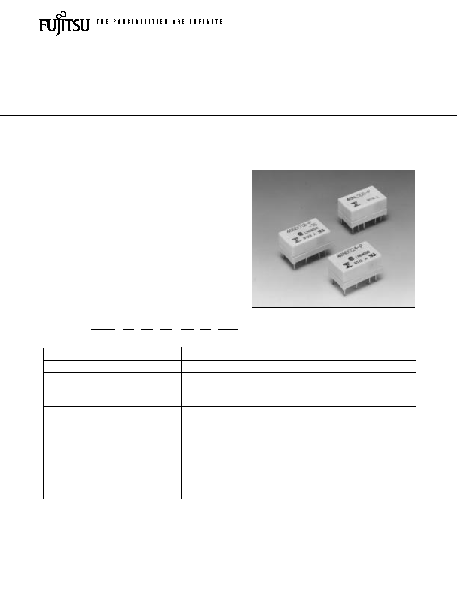
Miniature size
About 50% smaller in volume compared with the FBR240
series used mainly in communication equipment.
q
High surge voltage
2,500 V minimum of surge strength (Bellcore standard),
and 1,500 VAC minimum of dielectric strength between coil
and contact (-15, -16 type).
q
Low power consumption
85 mW of operate power (150 mW of nominal power con-
sumption) by built-in permanent magnet.
q
Shipping tube package
(a)
Series Name
FBR46 : FBR46 Series
(b)
Enclosure
N
: Plastic sealed
(*)
Coil Type
D
: Standard, -15, -16 (DC coil)
G
: 65% Operate type
L1
: Single winding latching type
L2
: Double winding latching type (refer to the SPECIFICATIONS)
(c)
Nominal Voltage
(Example) Standard, -15, -16 type
(Example) Latching type
005: 5 VDC
05: 5 VDC
012: 12 VDC
12: 12 VDC
(refer to the COIL DATA CHART)
(d)
Contact Material
≠P
: Gold-overlay silver-palladium
(e)
Dielectric Strength
Nil
: Between coil and contacts 1,000 VAC, between contacts 750 VAC
-15
: Between coil and contacts 1,500 VAC, between contacts 750 VAC
-16
: Between coil and contacts 1,500 VAC, between contacts 1,000 VAC
(f)
Safety Specification
Nil
: Standard (UL114 recognized)
-CSA : UL114 + CSA recognized
Note: The designation name is stamped on the top of the relay case as follows:
(Example) Designation ordered: FBR46ND012-P
Stamp: 46ND012-P
s
ORDERING INFORMATION
FBR46
N
D
012
-P -15
-CSA
[Example]
(a)
(b)
(*)
(c)
(d) (e)
(f )
FBR46 SERIES
MINIATURE RELAY
2 POLES--1 to 2 A
(FOR SIGNAL SWITCHING)
1
2
FBR46 SERIES
s
SAFETY STANDARD AND FILE NUMBERS
UL114 (File No. E63615)
C22.2 No. 14 (File No. LR40304 or LR64026)
Nominal voltage
Contact rating
1.5 to 24 VDC
1 A 30 VDC resistive
0.5 A 120 VAC resistive
* Excluding latching type FBR46L
Item
D type, G type
-15 type
-16 type
Latching
Contact
Arrangement and Style
2 form C (DPDT), bifurcated
Material
Gold-overlay silver-palladium
Resistance (initial)
Maximum 100 m
(at 0.1 A 6 VDC)
Ratings (resistive)
0.5 A 120 VAC or 1 A 30 VDC
Maximum Carrying Current
1.25 A
Maximum Switching Power
60 AV or 30 W
Max. Switching Voltage*
1
125 V
Maximum Switching Current
1 A
Minimum Switching load*
2
0.01 mA 10 mVDC (reference)
Electrostatic Capacity
Approximately 2 pF (between coil and contacts)
(reference) Approximately 1 pF (between open contacts)
Coil
Nominal power (at 20
∞
C)
0.15 to 0.2 W
0.2 to 0.25 W
0.2 W
0.25 W
Operate power (at 20
∞
C)
0.085 to 0.112
0.112 to 0.14 W maximum
0.128 W maximum
0.106 W maximum
Operating Temperature
≠30
∞
C to +70
∞
C (no frost) (refer to the CHARACTERISTIC DATA)
Operating Humidity
45 to 85%RH
Time Value
Operate (at nominal voltage)
Maximum 5 ms
Release (at nominal voltage)
Maximum 2 ms
Insulation
Resistance (initial)
Minimum 1000 M
(at 500 VDC)
Dielectric between coil and contacts
1,000 VAC 1,500 VAC
1,000 VAC
Strength between adjacent contacts
(for 1 minute)
between open contacts
750 VAC 1,000 VAC 750 VAC
between set-reset-coil
--
250 VAC
Surge
Strength between coil and contacts
1,500 V (at 10
◊
700
µ
s) 2,500 V (at 2
◊
10
µ
s) 1,500 V (at 10
◊
700
µ
s)
between adjacent contacts
between open contacts
1,500 V(at 10
◊
700
µ
s)
Continued
s
SPECIFICATIONS
2,500 V
1,250 V
2
µ
s
10
µ
s
1,500 V
750 V
10
µ
s
700
µ
s
3
FBR46 SERIES
Item
D type, G type
-15 type
-16 type
Latching
Life
Mechanical
50
◊
10
6
operations minimum
Electrical (refer to the DC
2
◊
10
5
operations minimum (at contact rating)
REFERENCE DATA)
AC
1
◊
10
5
operations minimum (at contact rating)
Other
Vibration Resistance
10 to 55 Hz (double amplitude of 1.5 mm)
Shock Misoperation
500 m/s
2
(11
±
1
ms)
Resistance
Endurance
1,000 m/s
2
(11
±
1
ms)
Weight
Approximately 2.5 g
*
1
If the switching voltage exceeds the rated contact voltage, reduce the current. The current values vary according to the
type of load.
*
2
Values when switching a resistive load at normal room temperature and humidity and in a clean environment. The mini-
mum switching load varies with the switching frequency and operation environment.
s
COIL DATA CHART
1. STANDARD (D type)
Nominal
Nominal
Coil
current
Must
Must
Nominal
Operate
Coil
MODEL
resistance
(at nominal
operate
release
temperature
voltage
(
±
10%)
voltage)
voltage*
1
voltage*
1
power
power
rise
approx.
FBR46ND003-P
3 VDC
60
50 mA
FBR46ND005-P
5 VDC
167
30 mA
FBR46ND006-P
6 VDC
240
25 mA
FBR46ND009-P
9 VDC
540
17 mA
FBR46ND012-P
12 VDC
960
13 mA
FBR46ND024-P
24 VDC
2,880
8 mA
200 mW
112 mW
30 deg
*1: Specified values are subject to pulse wave voltage.
Note: All values in the table are measured at 20
∞
C
75% max.
5% min.
Approx.
Approx.
Approx.
of nominal
of nominal
150 mW
85 mW
25 deg
voltage
voltage
(at nominal
max.
(at nominal
voltage
voltage)
2. 65% OPERATE TYPE (G type)
Nominal
Nominal
Coil
current
Must
Must
Nominal
Operate
Coil
MODEL
resistance
(at nominal
operate
release
temperature
voltage
(
±
10%)
voltage)
voltage*
1
voltage*
1
power
power
rise
approx.
FBR46NG003-P
3 VDC
36
83 mA
FBR46NG005-P
4.5 VDC
81
56 mA
FBR46NG006-P
6 VDC
144
41 mA
FBR46NG009-P
9 VDC
324
27 mA
FBR46NG012-P
12 VDC
576
20 mA
FBR46NG024-P
24 VDC
2,304
10 mA
*1: Specified values are subject to pulse wave voltage.
Note: All values in the table are measured at 20
∞
C
65% max.
10% min.
Approx.
Approx.
Approx.
of nominal
of nominal
250 mW
106 mW
35 deg
voltage
voltage
(at nominal
max.
(at nominal
voltage
voltage)
4
FBR46 SERIES
Nominal
MODEL
Nominal
Coil
current
Must
Must
Nominal
Operate
Coil
resistance (at nominal
operate
release
temperature
voltage
(
±
10%)
voltage)
voltage*
1
voltage*
1
power
power
rise
-15 type
-16 type
approx.
FBR46ND003-P-15 FBR46ND003-P-16
3 VDC
45
67 mA
FBR46ND005-P-15 FBR46ND005-P-16
5 VDC
125
40 mA
FBR46ND006-P-15 FBR46ND006-P-16
6 VDC
180
33 mA
FBR46ND009-P-15 FBR46ND009-P-16
9 VDC
405
22 mA
FBR46ND012-P-15 FBR46ND012-P-16
12 VDC
720
17 mA
FBR46ND024-P-15 FBR46ND024-P-16 24 VDC
2,304
10 mA
250 mW
140 mW
35 deg
*1: Specified values are subject to pulse wave voltage.
Note: All values in the table are measured at 20
∞
C.
3. HIGH DIELECTRIC STRENGTH TYPE (-15, -16 type)
75% max.
5% min.
Approx.
Approx.
Approx.
of
of
200 mW
112 mW
30 deg
nominal
nominal
(at nominal
max.
(at nominal
voltage
voltage
voltage)
voltage)
Nominal
MODEL
Coil
current
Must
Must
Nominal
resistance
(at nominal
operate
release
Nominal
Operate
Single winding
Double winding
voltage
(
±
10%)
voltage)
voltage*
1
voltage*
1
power
power
latching type
latching type
approx.
FBR46NL103-P
FBR46NL203-P
3 VDC
45
67 mA
FBR46NL105-P
FBR46NL205-P
5 VDC
125
40 mA
FBR46NL106-P
FBR46NL206-P
6 VDC
180
33 mA
FBR46NL109-P
FBR46NL209-P
9 VDC
405
22 mA
FBR46NL112-P
FBR46NL212-P
12 VDC
720
17 mA
*1: Specified values are subject to pulse wave voltage.
Note: All values in the table are measured at 20
∞
C.
4. LATCHING TYPE (L1, L2 type)
80% max. 80% max.
Approx.
Approx.
of nominal of nominal
200 mW
128 mW
voltage
voltage
(at nominal
max.
voltage)
5
FBR46 SERIES
s
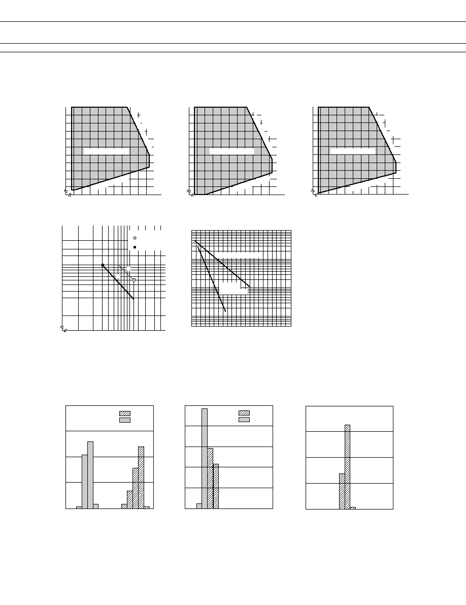
CHARACTERISTIC DATA
Life curve
500
Contact load current (A)
50
5
10
1
100
(
◊
10
4
)
Service life (operations)
0.5
1.0
1.5
2.0
30 V DC resistive load
Range of operation temperature and voltage
[D type]
Operating temperature (∞C)
≠10 0 10 20 30 40 50 60 70 80
70
80
90
100
110
120
130
140
150
160
Range of operation temperature and voltage
[G type]
≠10 0 10 20 30 40 50 60 70 80
70
80
90
100
110
120
130
140
150
160
Range of operation temperature and voltage
[≠15,≠16 type]
≠10 0 10 20 30 40 50 60 70 80
70
80
90
100
110
120
130
140
150
160
Maximum switching capacity
Contact load voltage (V)
0.1
10
20
120
200
30
50
0.3
0.5
1.0
Contact load current (A)
AC resistive load
( AC contact rating)
DC resistive load
( DC contact rating)
Operating voltage range
Must operate voltage
(Data) assumes that
the maximum
allowable tem-
perature of E
type insula-
tion coil is
115∞C
Maximum allowable coil voltage
Operating temperature (∞C)
Operating temperature (∞C)
Nominal voltage multiplying factor (%)
Nominal voltage multiplying factor (%)
Nominal voltage multiplying factor (%)
Must operate voltage
Must operate voltage
(Data) assumes that
the maximum
allowable tem-
perature of E
type insula-
tion coil is
115∞C
(Data) assumes that
the maximum
allowable tem-
perature of E
type insula-
tion coil is
115∞C
Maximum allowable coil voltage
Maximum allowable coil voltage
120 V AC
resistive load
Operating voltage range
Operating voltage range
s
REFERENCE DATA
Operate
Release
Distribution of operate and release voltage
Rated coil voltage multiplying factor (%)
80
60
40
20
0
0
10
20
30
40
50
60
70
80
Operate
Release
Distribution of operate and release time
Time (ms)
100
80
60
20
40
0
1
2
3
4
5
6
7
8
0
Contact resistance (m
)
Distribution of contact resistance
80
60
40
20
0
10
20
30
40
50
60
70
80
0
Distribution (%)
Distribution (%)
Distribution (%)
6
FBR46 SERIES
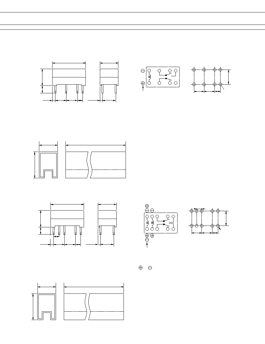
q
Dimensions
q
Schematics
(BOTTOM VIEW)
q
PC board mounting hole
layout (BOTTOM VIEW)
q
Tube carrier
5.08
(1.0)
7.9
+
0.1
3.5
12.8 max.
15.8 maximum
501 maximum
5.08
7.62
(1.09)
.54
15.9
+0.1
9.8
+0.1
1
3
5 6
12
10
8 7
Polarity
5.08
7.62
5.08 2.54
8≠¯0.8
s
DIMENSIONS
q
Dimensions (Latching type)
q
Schematics
(BOTTOM VIEW)
q
PC board mounting hole
layout (BOTTOM VIEW)
q
Tube carrier
5.08
7.9
+
0.1
3.5
12.8 max.
15.8 maximum
501 maximum
5.08
2.54
15.9
+0.1
9.8
+0.1
1
3
5 6
12
10
8 7
polarity
5.08
7.62
5.08 2.54
10≠¯0.8
Note: ∑No 2, 11 terminals are for double winding latching type only.
∑( ) ( ) are reset polarity for single winding latching type.
∑The terminal number is not shown on the relay.
V
2
11
( )
2.54
( )
(1.0)
7.62
(1.09)
2.54
Unit: mm

7
FBR46 SERIES
© 2003 Fujitsu Components America, Inc. All company and product names are trademarks or registered trademarks
of their respective owners. Rev. 02/12/2003
Japan
Fujitsu Component Limited
Gotanda-Chuo Building
3-5, Higashigotanda 2-chome, Shinagawa-ku
Tokyo 141, Japan
Tel: (81-3) 5449-7010
Fax: (81-3) 5449-2626
Email: promothq@ft.ed.fujitsu.com
Web: www.fcl.fujitsu.com
North and South America
Fujitsu Components America, Inc.
250 E. Caribbean Drive
Sunnyvale, CA 94089 U.S.A.
Tel: (1-408) 745-4900
Fax: (1-408) 745-4970
Email: marcom@fcai.fujitsu.com
Web: www.fcai.fujitsu.com
Europe
Fujitsu Components Europe B.V.
Diamantlaan 25
2132 WV Hoofddorp
Netherlands
Tel: (31-23) 5560910
Fax: (31-23) 5560950
Email: info@fceu.fujitsu.com
Web: www.fceu.fujitsu.com
Asia Pacific
Fujitsu Components Asia Ltd.
102E Pasir Panjang Road
#04-01 Citilink Warehouse Complex
Singapore 118529
Tel: (65) 6375-8560
Fax: (65) 6273-3021
Email: fcal@fcal.fujitsu.com
www.fcal.fujitsu.com
Fujitsu Components
International
Headquarter
Offices