(a)
Series Name
FBR51 : Standard type (contact gap 0.3 mm)
FBR52 : Wider contact gap type (contact gap 0.6 mm)
(b)
Enclosure
N
: Plastic sealed type
(c)
Nominal Voltage
D06
: 6 VDC
D09
: 9 VDC
D10
: 10 VDC
D12
: 12 VDC
(d)
Contact Material
W
: Silver-tin oxide indium
W1
: Silver-tin oxide indium (high power type)
WL
: Silver-tin oxide indium (1 lamp loads, see applications table)
(e)
Custom Designation
To be assigned custom specification
s
FEATURES
q
Compact and lightweight structure
(42% of the volume of the FBR160 relay)
q
High current contact capacity
(carrying current: 35 A/10 minutes, 25 A/1 hour)
q
High resistance to vibration and shock
q
Improved heat resistance and extended operation range
q
Two contact gap options
(FBR51: 0.3 mm, FBR52: 0.6 mm)
q
Three types of contact material
s
ORDERING INFORMATION
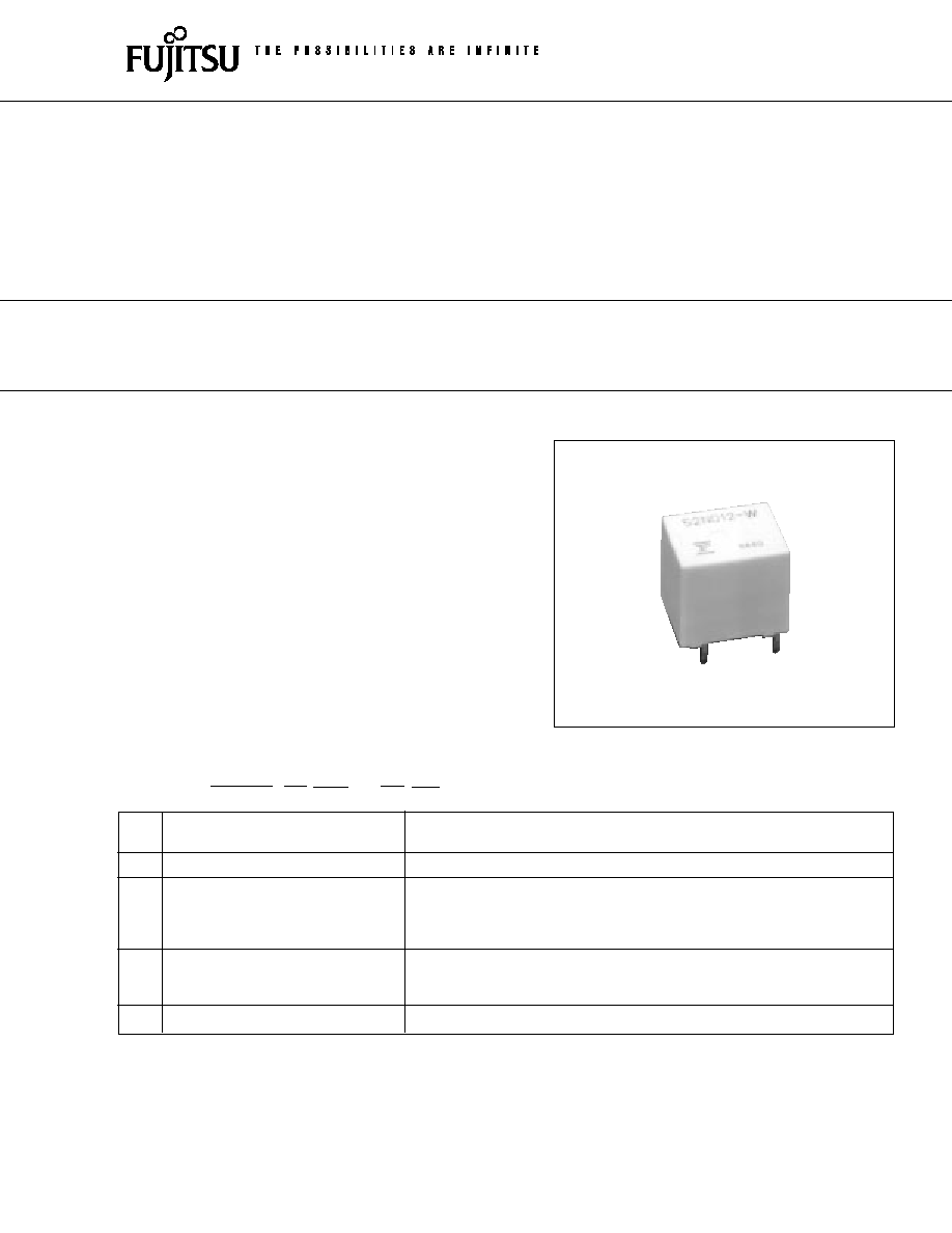
FBR51, 52 SERIES
COMPACT POWER RELAY
1 POLE--25 A
(FOR AUTOMOTIVE APPLICATIONS)
FBR51
N
D12
≠
W
**
[Example]
(a)
(b)
(c)
(d)
(e)
1

2
FBR51, 52 SERIES
s
SPECIFICATIONS
*1 Values when switching a resistive load at normal room temperature and humidity and in a clean environment.
The minimum switching load varies with the switching frequency and operating environment.
m
e
t
I
s
n
o
i
t
a
c
i
f
i
c
e
p
S
t
c
a
t
n
o
c
W
t
c
a
t
n
o
c
1
W
t
c
a
t
n
o
c
L
W
t
c
a
t
n
o
C
t
n
e
m
e
g
n
a
r
r
A
)
T
D
P
S
(
C
m
r
o
f
1
A
m
r
o
f
1
)
T
S
P
S
(
l
a
i
r
e
t
a
M
e
d
i
x
o
n
i
t
-
r
e
v
li
S
m
u
i
d
n
i
e
d
i
x
o
n
i
t
-
r
e
v
li
S
m
u
i
d
n
i
h
g
i
h
(
)
e
p
y
t
r
e
w
o
p
e
d
i
x
o
n
i
t
-
r
e
v
li
S
m
u
i
d
n
i
)
e
c
n
a
t
s
i
s
e
R
(
p
o
r
D
e
g
a
t
l
o
V
)
C
D
V
2
1
A
2
t
a
(
V
m
0
0
1
m
u
m
i
x
a
M
g
n
i
t
a
R
A
0
2
C
D
V
4
1
)
d
a
o
l
e
e
r
f
r
o
t
o
m
(
A
5
2
C
D
V
4
1
)
d
a
o
l
e
e
r
f
r
o
t
o
m
(
p
m
a
l
t
t
a
W
5
1
1
C
D
V
4
1
t
a
t
n
e
r
r
u
C
g
n
i
y
r
r
a
C
m
u
m
i
x
a
M
d
e
t
a
r
%
0
0
1
,
C
∞
5
2
(
r
u
o
h
1
/
A
5
2
,
s
e
t
u
n
i
m
0
1
/
A
5
3
)
e
g
a
t
l
o
v
li
o
c
t
n
e
r
r
u
C
h
s
u
r
n
I
m
u
m
i
x
a
M
)
e
c
n
e
r
e
f
e
R
(
A
0
6
A
0
4
t
n
e
r
r
u
C
g
n
i
h
c
t
i
w
S
.
x
a
M
(
)
e
c
n
e
r
e
f
e
R
C
D
V
6
1
A
5
3
*
d
a
o
L
g
n
i
h
c
t
i
w
S
.
n
i
M
1
)
e
c
n
e
r
e
f
e
R
(
A
1
C
D
V
6
li
o
C
e
r
u
t
a
r
e
p
m
e
T
g
n
i
t
a
r
e
p
O
e
g
n
a
R
)
t
s
o
r
f
o
n
(
C
∞
5
8
+
o
t
C
∞
0
4
-
e
g
n
a
R
e
r
u
t
a
r
e
p
m
e
T
e
g
a
r
o
t
S
)
t
s
o
r
f
o
n
(
C
∞
0
0
1
+
o
t
C
∞
0
4
-
e
m
i
T
e
u
l
a
V
)
e
g
a
t
l
o
v
l
a
n
i
m
o
n
t
a
(
e
t
a
r
e
p
O
s
m
0
1
m
u
m
i
x
a
M
)
e
g
a
t
l
o
v
l
a
n
i
m
o
n
t
a
(
e
s
a
e
l
e
R
s
m
5
m
u
m
i
x
a
M
e
f
i
L
l
a
c
i
n
a
h
c
e
M
0
1
x
0
1
6
m
u
m
i
n
i
m
s
n
o
i
t
a
r
e
p
o
l
a
c
i
r
t
c
e
l
E
0
1
x
2
5
.
n
i
m
.
s
p
o
A
0
2
C
D
V
4
1
r
o
t
o
m
d
e
k
c
o
L
d
a
o
l
0
1
x
2
5
.
n
i
m
.
s
p
o
A
5
2
C
D
V
4
1
r
o
t
o
m
d
e
k
c
o
L
d
a
o
l
0
1
x
5
.
2
5
.
s
p
o
.
n
i
m
s
t
t
a
W
5
1
1
C
D
V
4
1
,
p
m
a
l
r
e
h
t
O
e
c
n
a
t
s
i
s
e
R
s
n
o
i
t
a
r
b
i
V
)
m
m
5
.
1
f
o
e
d
u
t
il
p
m
a
e
l
b
u
o
d
(
z
H
5
5
o
t
0
1
k
c
o
h
S
e
c
n
a
t
s
i
s
e
R
n
o
i
t
a
r
e
p
o
s
i
M
s
/
m
0
0
1
2
e
c
n
a
r
u
d
n
E
s
/
m
0
0
0
,
1
2
t
h
g
i
e
W
g
6
y
l
e
t
a
m
i
x
o
r
p
p
A

3
FBR51, 52 SERIES
MODEL
Nominal
Coil
Must operate
Thermal
voltage
resistance
voltage
resistance
W contact
W1 contact
(
±
10%) (at 20
∞
C)
FBR51ND06-W FBR51ND06-W1
6 VDC
60
3.6 VDC (at 20
∞
C)
4.5 VDC (at 85
∞
C)
FBR51ND09-W FBR51ND09-W1
9 VDC
135
5.4 VDC (at 20
∞
C)
6.8 VDC (at 85
∞
C)
73
∞
C/W
FBR51ND10-W FBR51ND10-W1
10 VDC
180
6.3 VDC (at 20
∞
C)
7.9 VDC (at 85
∞
C)
FBR51ND12-W FBR51ND12-W1
12 VDC
240
7.3 VDC (at 20
∞
C)
9.2 VDC (at 85
∞
C)
s
COIL DATA CHART
1. FBR51 Series
2. FBR52 Series
MODEL
Nominal
Coil
Must operate
Thermal
voltage
resistance
voltage
resistance
W contact
W1 contact
(
±
10%) (at 20
∞
C)
FBR52ND06-W FBR52ND06-W1
6 VDC
45
3.6 VDC (at 20
∞
C)
4.5 VDC (at 85
∞
C)
FBR52ND09-W FBR52ND09-W1
9 VDC
100
5.4 VDC (at 20
∞
C)
6.8 VDC (at 85
∞
C)
65
∞
C/W
FBR52ND10-W FBR52ND10-W1
10 VDC
135
6.3 VDC (at 20
∞
C)
7.9 VDC (at 85
∞
C)
FBR52ND12-W FBR52ND12-W1
12 VDC
180
7.3 VDC (at 20
∞
C)
9.2 VDC (at 85
∞
C)
4
FBR51, 52 SERIES
s
SUITABLE APPLICATIONS
Recommended
Normal load current
model (example)
Application
(12 VDC system)
Description
For 16 V or less
For instantaneous
motor load voltage
20 V or more load voltage
Power Windows
20 to 25 A
forward and reverse
FBR51N
s
s
-W
FBR52N
s
s
-W
(switching at motor locking)
motor control
FBR51N
s
s
-W1
FBR52N
s
s
-W1
Automatic Door Lock
18 to 25 A
forward and reverse
FBR51N
s
s
-W
FBR52N
s
s
-W
(switching at motor locking)
motor control
FBR51N
s
s
-W1
FBR52N
s
s
-W1
Tilt-Lock Wheel
20 A
forward and reverse
FBR51N
s
s
-W
FBR52N
s
s
-W
(switching at motor locking)
motor control
Sunroof
20 to 30 A
forward and reverse
FBR51N
s
s
-W
FBR52N
s
s
-W
(switching at motor locking)
motor control
Adjustable Door Mirror
3 to 5 A
forward and reverse
FBR51N
s
s
-W
(switching at motor locking)
motor control
8 to 12 A (INRUSH)
forward and reverse
Automatic Antenna
break 2 A maximum
motor control
FBR51N
s
s
-W
(motor-free)
Auto-Cruise
2 to 3 A
power shutoff and solenoid
FBR51N
s
s
-W
Lamp loads
115 Watts
for up to 250K operations
FBR51N
s
s
-WL
Others
Car Audio System, etc.
FBR51N
s
s
-W
∑ For the load condition where higher voltage would be encountered during contact break, FBR52 series with wider contact
gap is recommended.
s
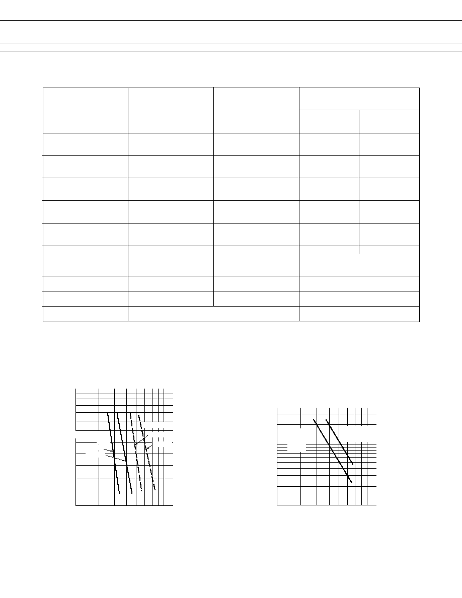
CHARACTERISTIC DATA
1. MAXIMUM BREAK CAPACITY
2. LIFE
Voltage between contacts (VDC)
10
10
15
12
20
25
30
35
40
50
Contact switching current (A)
20
15
25
35
30
40 50
FBR51
FBR52
Locked motor
load
FBR51
FBR52
Resistive load
Locked motor current (A)
14 VDC Motor locked load
10
5
10
20
30
Number of operations (x10
4
)
20
15
25
35
30
40 50
Standard
type
(--W)
High power type
(--W1)
5
FBR51, 52 SERIES
0
100
10
1
20
40
60
80
100
(RL-1)
20 sec
20 A
0 A
20 A
0 A
(RL-2)
0.3 sec
10 sec
0.3 sec
100
10
1
1000
100
10
(measured at 6 V-1 A)
0
100
10
1
20
40
60
80
100
100
10
1
1000
m
100
10
(measured at 6 V-1 A)
M
N.O.
N.C.
0 A
4 A
20 A
16 A
M
RL-1
RL-2
N.O.
N.C.
N.O.
N.C.
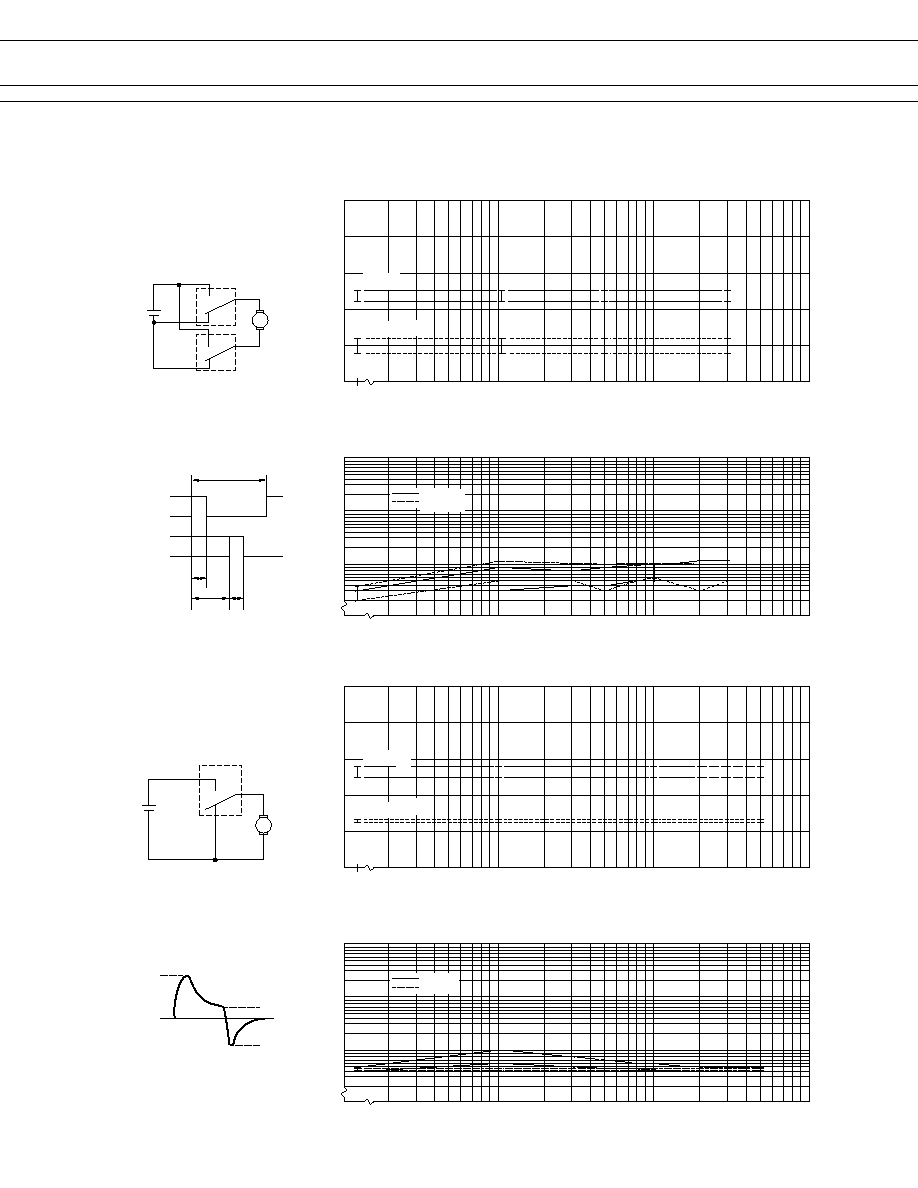
3. LIFE TEST (EXAMPLE)
∑ Test item
14 V DC-20 A
motor lock 200,000
operations minimum
(FBR52
s
s
-W type)
∑ Test circuit
∑ Current wave form
∑ Shift of pick-up drop-out voltage
∑ Shift of contact resistance
∑ Test item
14 V DC-20 A
motor free 400,000
operations minimum
(FBR51
s
s
-N type)
∑ Test circuit
∑ Current wave form
∑ Shift of pick-up drop-out voltage
∑ Shift of contact resistance
PICK-UP
Initial
Percent of rated coil voltage (%)
Number of operations (x10
4
)
Break
Make
Contact Resistance (m
)
Initial
Initial
Percent of rated coil voltage (%)
Number of operations (x10
4
)
Break
Make
Contact Resistance (m
)
Initial
PICK-UP
DROP-OUT
DROP-OUT
6
FBR51, 52 SERIES
∑ Shift of pick-up and drop-out voltage
No. of operations (x10
4
)
% of rated coil voltage
0
100
10
1
20
40
60
80
100
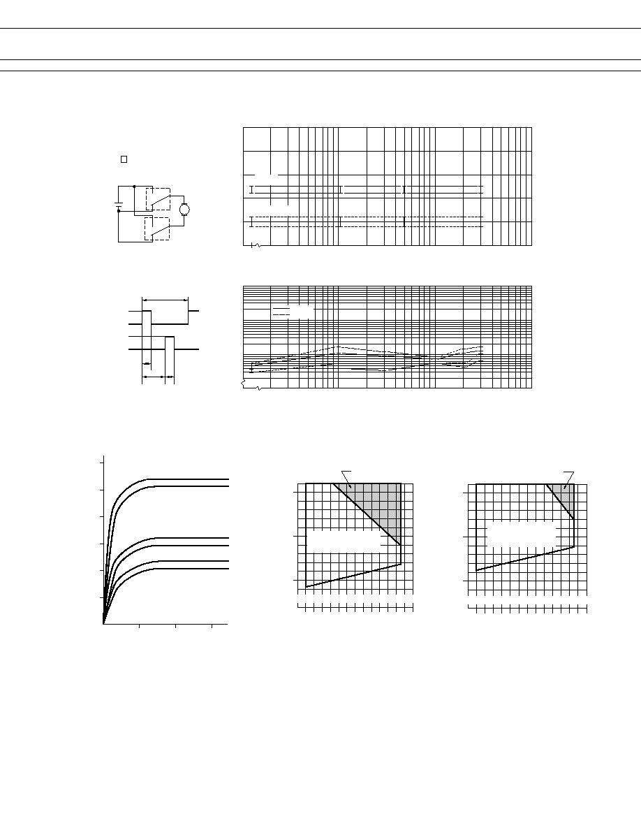
∑ Test item
14 V DC-25 A
Motor lock
200,000 operations minimum
(FBR51 -W1 type)
∑ Current wave form
∑ Test circuit
(RL-1)
20 sec
25 A
0 A
25 A
0 A
(RL-2)
0.3 sec
10 sec
0.3 sec
∑ Shift of contact resistance
100
10
1
1000
100
10
Break
Make
(measured at 6 V-1 A)
M
RL-1
RL-2
N.O.
N.C.
N.O.
N.C.
PICK-UP
DROP-OUT
Contact resistance
No. of operations (x10
4
)
4. COIL TEMPERATURE RISE
5. OPERATING COIL VOLATGE RANGE (EXAMPLE)
Coil temperature rise
(
∞C
)
Applied time (minutes)
0
0
10
20
30
20
40
60
80
100
120
0.8 W
at 20∞C
0.6 W
(2) carrying current : 10 A
applied coil power
0.8 W
0.6 W
(1)carrying current : 0 A
applied coil power
0.8 W
0.6 W
(3) carrying current : 20 A
applied coil power
≠30
0
50
100
5
10
15
Applied voltage to the coil
Operating temperature (∞C)
NOTE : Intermittent coil
operation is required in this
region at 20 A or more
carrying current.
(V)
CONTINUOUSLY
APPLICABLE COIL
VOLTAGE RANGE
Applied voltage to the coil
Operating temperature (∞C)
NOTE : Intermittent coil
operation is required in this
region at 20 A or more
carrying current.
≠30
0
50
100
5
10
15
(V)
CONTINUOUSLY
APPLICABLE COIL
VOLTAGE RANGE
[ FBR51ND09-
s
s
]
[ FBR51ND12-
s
s
]

7
FBR51, 52 SERIES
6. VIBRATION RESISTANCE CHARACTERISTICS
7. SHOCK RESISTANCE CHARACTERISTICS
FBR51
Y
Z
X
Frequency : 10~2000 Hz
Acceleration : 100 m/s
2
max
Direction of vibration : see under diagram
Detection level : chatter > 100 s
Acceleration
(m/s
2
)
10
50
100
10
50
100
500
1000
2000
5
1
0.5
0.1
0.01
Dual amplitude (mm)
Frequency (Hz)
Automotive
electronics standard
44 m/s
2
Range where chattering occurs
N.O. contact
coil not energized
on X-direction
0
200
400
600
800
1,000
X1
X2
Y1
Y2
Z1
Z2
Shock level
(m/s
2
)
Shock direction
: N.C. contact
(coil de-energized)
Shock application time : 11 ms, half-sine wave
Test material : coil, energized and de-energized
Shock direction : set under diagram
Detection level : chatter > 100 s
FBR51
Z2
Z1
Y1
Y2
X2
X1
: N.C. Contact
(coil energized)
s
REFERENCE DATA
FBR52
n = 100
Operate
Release
Distribution of operate and release voltage
Nominal voltage multiplying factor (%)
80
60
40
20
0
10 20 30 40 50 60 70 80
0
Distribution (%)
FBR52
n = 100
Operate
Release
Distribution of operate and release time
Time (ms)
100
80
60
20
40
0
1
2
3
4
5
6
7
8
0
Distribution (%)
Contact resistance (m
)
Distribution of contact resistance
FBR52
n = 100
100
80
60
20
40
0
10 20 30 40 50 60 70 80
0
Distribution (%)

8
FBR51, 52 SERIES
s
DIMENSIONS
45 pcs/tube
20.3 Max.
601 Max.
q
Dimensions
19.0 Max.
51ND12-W
F
9427
q
PC board mounting hole layout
(BOTTOM VIEW)
q
Schematics
(BOTTOM VIEW)
4-¯ 1.3
COM
N.C.
N.O.
q
Tube carrier
Unit : mm
12.1
+0.2
15.5
+0.2
R0.4
R0.4
13.7
+0.3
0.3
2.5
10.2
1
t = 0.4
1
(1.6)
(1.05)
3.5
10
5
1.2
t = 0.3
5
10
10.2
2.5
¯ 1.4
© 2003 Fujitsu Components America, Inc. All company and product names are trademarks or registered trademarks
of their respective owners. Rev. 02/18/2003
Japan
Fujitsu Component Limited
Gotanda-Chuo Building
3-5, Higashigotanda 2-chome, Shinagawa-ku
Tokyo 141, Japan
Tel: (81-3) 5449-7010
Fax: (81-3) 5449-2626
Email: promothq@ft.ed.fujitsu.com
Web: www.fcl.fujitsu.com
North and South America
Fujitsu Components America, Inc.
250 E. Caribbean Drive
Sunnyvale, CA 94089 U.S.A.
Tel: (1-408) 745-4900
Fax: (1-408) 745-4970
Email: marcom@fcai.fujitsu.com
Web: www.fcai.fujitsu.com
Europe
Fujitsu Components Europe B.V.
Diamantlaan 25
2132 WV Hoofddorp
Netherlands
Tel: (31-23) 5560910
Fax: (31-23) 5560950
Email: info@fceu.fujitsu.com
Web: www.fceu.fujitsu.com
Asia Pacific
Fujitsu Components Asia Ltd.
102E Pasir Panjang Road
#04-01 Citilink Warehouse Complex
Singapore 118529
Tel: (65) 6375-8560
Fax: (65) 6273-3021
Email: fcal@fcal.fujitsu.com
www.fcal.fujitsu.com
Fujitsu Components
International
Headquarter
Offices