s
FEATURES
q
Two independent relays mounted in a single package
(43% of the volume of the two FRL-270 relays)
q
High current contact capacity
(carrying current: 40 A/2 minutes, 30 A/1 hour)
q
High heat resistance and extended operating voltage
s
ORDERING INFORMATION
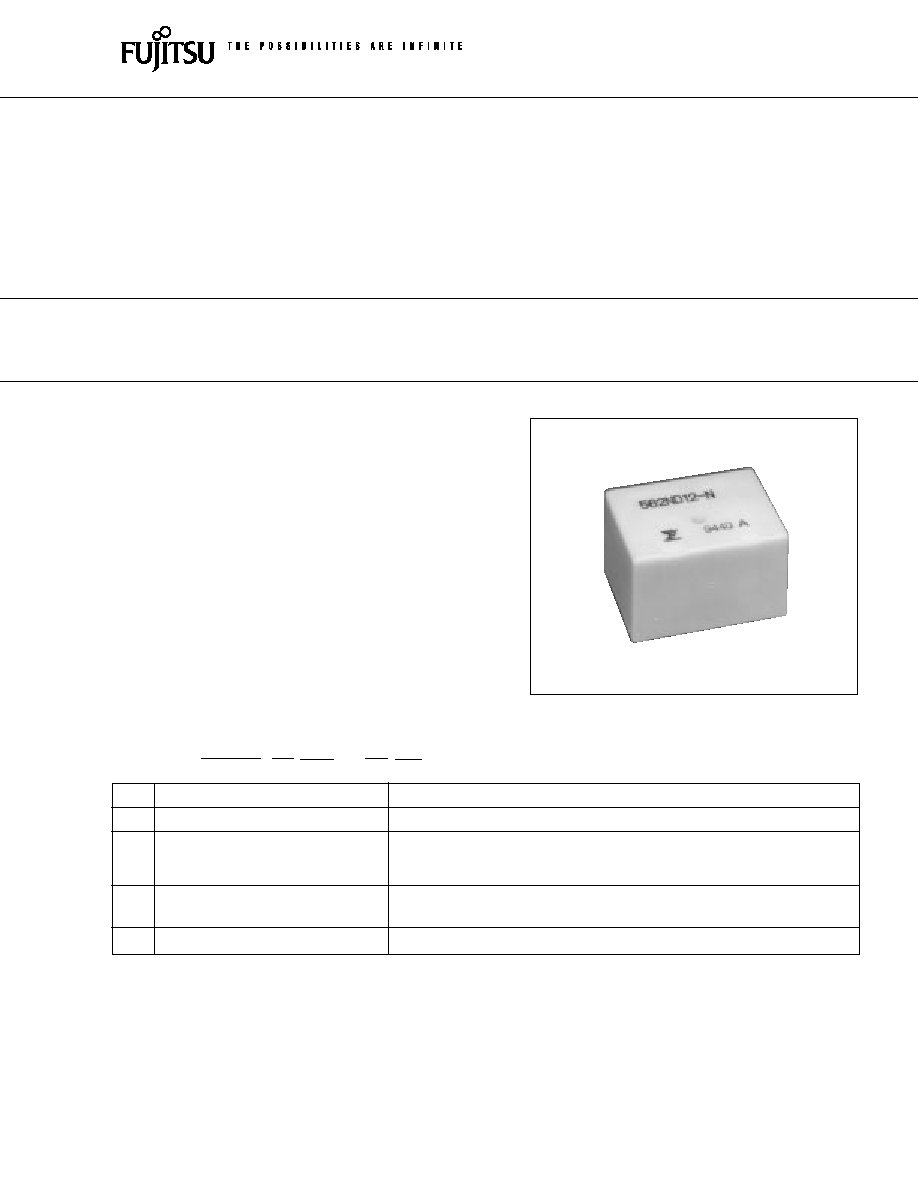
FBR562 SERIES
HIGH POWER TWIN RELAY
1 POLE x 2--30A
(FOR AUTOMOTIVE APPLICATIONS)
(a)
Series Name
FBR562: FBR562 Series relay for 12 V battery (contact gap 0.4 mm)
(b)
Enclosure
N
: Plastic sealed type
(c)
Nominal Voltage
D06
: 6 VDC
D09
: 9 VDC
D12
: 12 VDC
(d)
Contact Material
W
: Silver-tin oxide indium
N
: Silver copper nickel
(e)
Custom Designation
To be assigned custom specification
FBR562
N
D12
≠
W
**
[Example]
(a)
(b)
(c)
(d)
(e)
1
2
FBR562 SERIES
s
COIL DATA CHART
MODEL
Nominal
Coil
Must operate
Thermal
voltage
resistance
voltage
resistance
W contact
N contact
(
±
10%) (at 20
∞
C)
FBR562ND06-W
FBR562ND06-N
6 VDC
42
3.6 VDC (at 20
∞
C)
4.5 VDC (at 85
∞
C)
FBR562ND09-W
FBR562ND09-N
9 VDC
95
5.4 VDC (at 20
∞
C)
77
∞
C/W
6.8 VDC (at 85
∞
C)
FBR562ND12-W
FBR562ND12-N
12 VDC
170
7.3 VDC (at 20
∞
C)
9.2 VDC (at 85
∞
C)
s
SPECIFICATIONS
Item
Specifications
Contact
Arrangement
1 form C
◊
2 (SPDT
◊
2)
Material
Silver-tin oxide indium (≠W type)
Silver copper nickel (≠N type)
Voltage Drop (resistance)
Maximum 100 mV (at 2 A 12 VDC)
Ratings
14 VDC 20 A (locked motor load)
14 VDC inrush 20 A, break 4 A (motor free load)
Maximum Carrying Current
40 A/2 minutes, 30 A/ 1 hour
(25
∞
C, 100% rated coil voltage)
Maximum Inrush Current
≠W type: 60 A
(reference)
≠N type: 40 A
Max. Switching Current (reference)
40 A 16 VDC
Minimum Switching Load*
1
≠W type: 6 VDC 1 A
(reference)
≠N type: 6 VDC 2 A
Coil
Operating Temperature
≠40
∞
C to +85
∞
C (no frost) (refer to the CHARACTERISTIC DATA)
Storage Temperature
≠40
∞
C to +100
∞
C (no frost)
Time Value
Operate (at nominal voltage)
Maximum 10 ms
Release (at nominal voltage)
Maximum 5 ms
Life
Mechanical
1
◊
10
7
operations minimum
Electrical
1
◊
10
5
operations minimum (locked motor load)
1
◊
10
6
operations minimum (motor free Load)
Other
Vibration Resistance
10 to 55 Hz (double amplitude of 1.5 mm)
Shock Misoperation
100 m/s
2
Resistance
Endurance
1,000 m/s
2
Weight
Approximately 18 g
*1 Values when switching a resistive load at normal room temperature and humidity and in a clean environment.
The minimum switching load varies with the switching frequency and operating environment.
3
FBR562 SERIES
s
SUITABLE APPLICATIONS
Application
Normal load current
Life x 10
3
Recommended
model (example)
Power Windows
20 to 30 A (switching at motor locking)
100
FBR562N
s
s
-W
Automatic Door Lock
18 to 30 A/4 to 5 door (switching at motor locking)
100
FBR562N
s
s
-W
Intermittent Wipers
INRUSH 15 to 30 A
300
FBR562N
s
s
-N
For 12 V
BREAK 2 to 8 A (motor free)
battery
Tilt-Lock Wheel
INRUSH 15 A
100
FBR562N
s
s
-W
BREAK 2.5 A (motor free)
Sunroof
20 to 30 A (switching at motor locking)
100
FBR562N
s
s
-W
Others
Car audio system, etc
--
FBR562N
s
s
-W
s
CHARACTERISTIC DATA
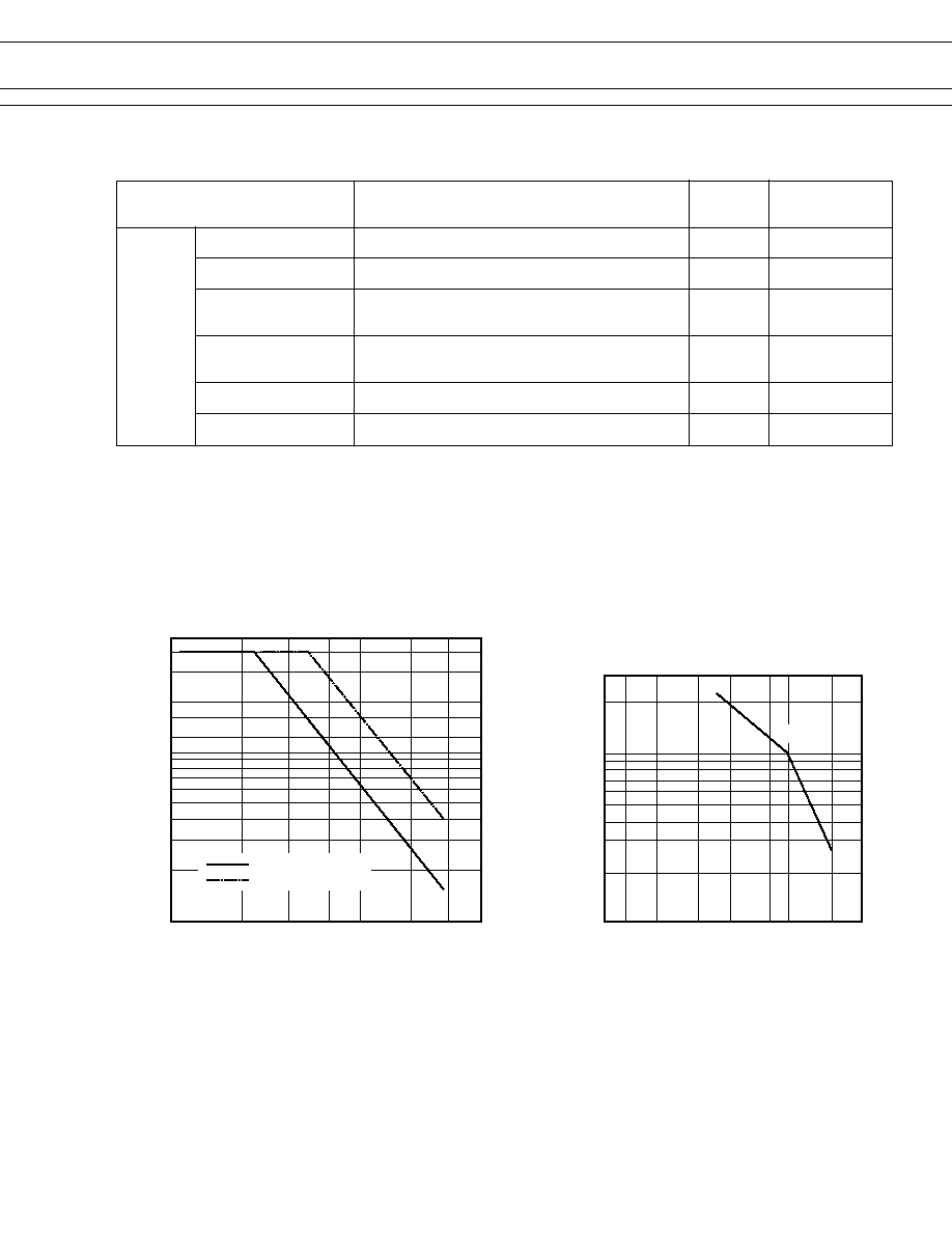
1. MAXIMUM BREAK CAPACITY
2. LIFE
Locked motor load
Resistive load
Contact switching current (A)
50
20
15
12
10
5
1
10
15
20
25
30
40
50
Voltage between contacts (VDC)
Number of operations (x10
4
)
14 VDC
30
20
10
5
3
8 10
12
15
20
30
40
50
Locked motor current (A)
4
FBR562 SERIES
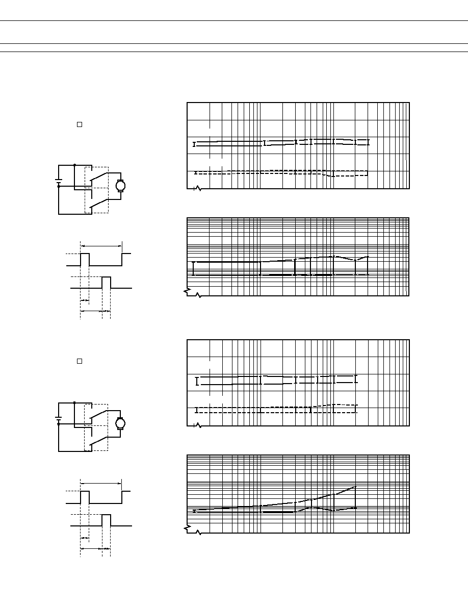
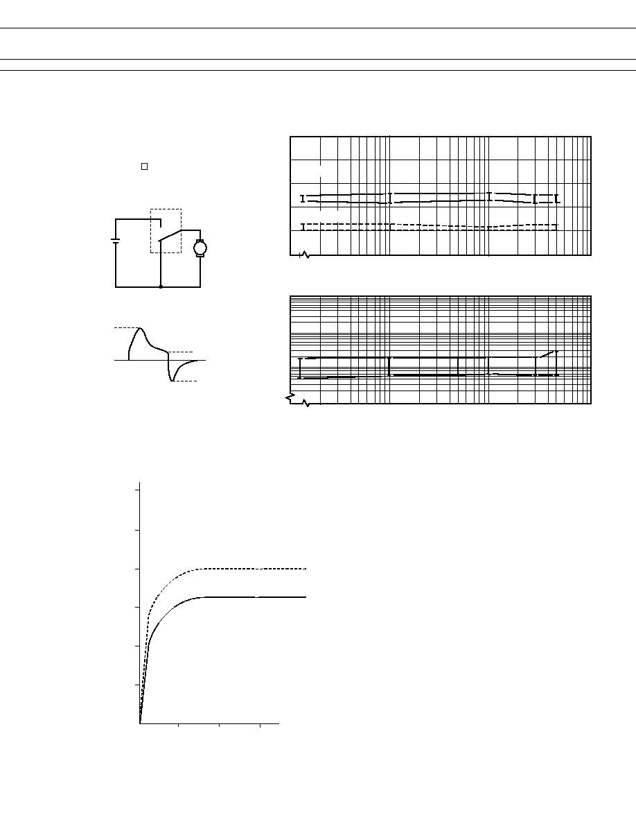
3. LIFE TEST (EXAMPLE)
(Continued)
20 sec
(RL-1)
20 A
0 A
(RL-2)
0.3 sec
10 sec
0.3 sec
∑ Current Wave Form
∑ Test circuit
RL-1
N.O.
N.C.
N.O.
N.C.
M
RL-2
20 sec
(RL-1)
30 A
0 A
(RL-2)
0.3 sec
10 sec
0.3 sec
∑ Current wave form
∑ Test circuit
RL-1
N.O.
N.C.
N.O.
N.C.
M
RL-2
Ratio of pick-up and
drop-out values
to rated coil voltages
(%) 100
80
60
40
20
0
PICK-UP
DROP-OUT
Initial
1
10
100
∑ Shift of pick-up drop-out voltage
Initial
1
10
100
No. of operations (x 10
4
)
∑ Shift of contact resistance
CONTACT RESISTANCE
m
1000
100
10
(measured at 6 V-1 A)
Ratio of pick-up and
drop-out values
to rated coil voltages
(%) 100
80
60
40
20
0
PICK-UP
DROP-OUT
Initial
1
10
100
∑ Shift of pick-up drop-out voltage
Initial
1
10
100
No. of operations (x 10
4
)
∑ Shift of contact resistance
CONTACT RESISTANCE
m
1000
100
10
(measured at 6 V-1 A)
∑ Test item
14 VDC-20 A
Motor lock
200,000 operations minimum
(FBR562 -W type)
∑ Test item
14 VDC-30 A
Motor lock
100,000 operations minimum
(FBR562 -W type)
5
FBR562 SERIES
(Continued)
∑ Current wave form
∑ Test circuit
N.O.
N.C.
Ratio of pick-up and
drop-out values
to rated coil voltages
(%) 100
80
60
40
20
0
PICK-UP
DROP-OUT
Initial
1
10
100
∑ Shift of pick-up drop-out voltage
Initial
1
10
100
No. of operations (x10
4
)
∑ Shift of contact resistance
CONTACT RESISTANCE
m
1000
100
10
(measured at 6 V-1 A)
4 A
16 A
25 A
0 A
M
∑ Test item
16 VDC-25 A INRUSH
Motor Free
400,000 operations minimum
(FBR562 -N type)
4. COIL TEMPERATURE RISE
(1)
(2)
Coil temperature rise (
∞C
)
120
100
80
60
40
20
0
Applied time (minutes)
0
10
20
30
*: One coil energized at 20∞C
If both coils are energized, temperature
rise will increase by
(1) 5∞C (0 A carrying current)
(2) 20∞C (10 A carrying current)
6
FBR562 SERIES
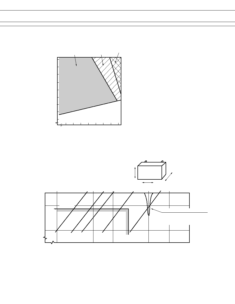
5. OPERATING COIL VOLTAGE RANGE (EXAMPLE)
Ratio of operating
voltage to rated
coil voltage (%)
133
130
120
110
100
90
80
70
60
50
10
20
30
40
50
60
70
80 85
Operating temperature (∞C)
Operating voltage
Continuous at carrying
current of 20 A
Within 5 minutes
at carrying current
of 20 A
Within 3 minutes
at carrying current
of 20 A
6. VIBRATION RESISTANCE CHARACTERISTICS
Dual amplitude
Frequency (Hz)
Acceleration
(G)
4.4 G
10
1
Automotive
electronics
standard
10
50
100
200
600
1000
2000
5
1
0.5
0.1
0.01
X
Y
Z
FBR562
Range where chattering occurs
N.O.contact
coil not energized
on X-direction

7
FBR562 SERIES
7. SHOCK RESISTANCE CHARACTERISTICS
X1
Y2
Z1
FBR562
Y1
Z2
X2
Shock direction
X1
X2
Y2
Z1
Z2
Y1
100
80
60
40
20
0
Shock
level
(G)
: N.C. contact (coil de-energized)
: N.O. Contact (coil energized)
s
REFERENCE DATA
80
60
40
20
0 10 20 30 40 50 60 70 80
0
Distribution (%)
FBR562
n = 100
Operate
Release
Distribution of operate and release voltage
Nominal voltage multiplying factor (%)
80
100
60
40
20
0
1
2
3
4
5
6
7
8
0
FBR562
n = 100
Operate
Release
Distribution of operate and release time
Time (ms)
0 10 20 30 40 50 60 70 80
100
80
60
40
20
0
FBR562
n = 100
Distribution of contact resistance
Contact resistance (m
)
Distribution (%)
Distribution (%)
8
FBR562 SERIES
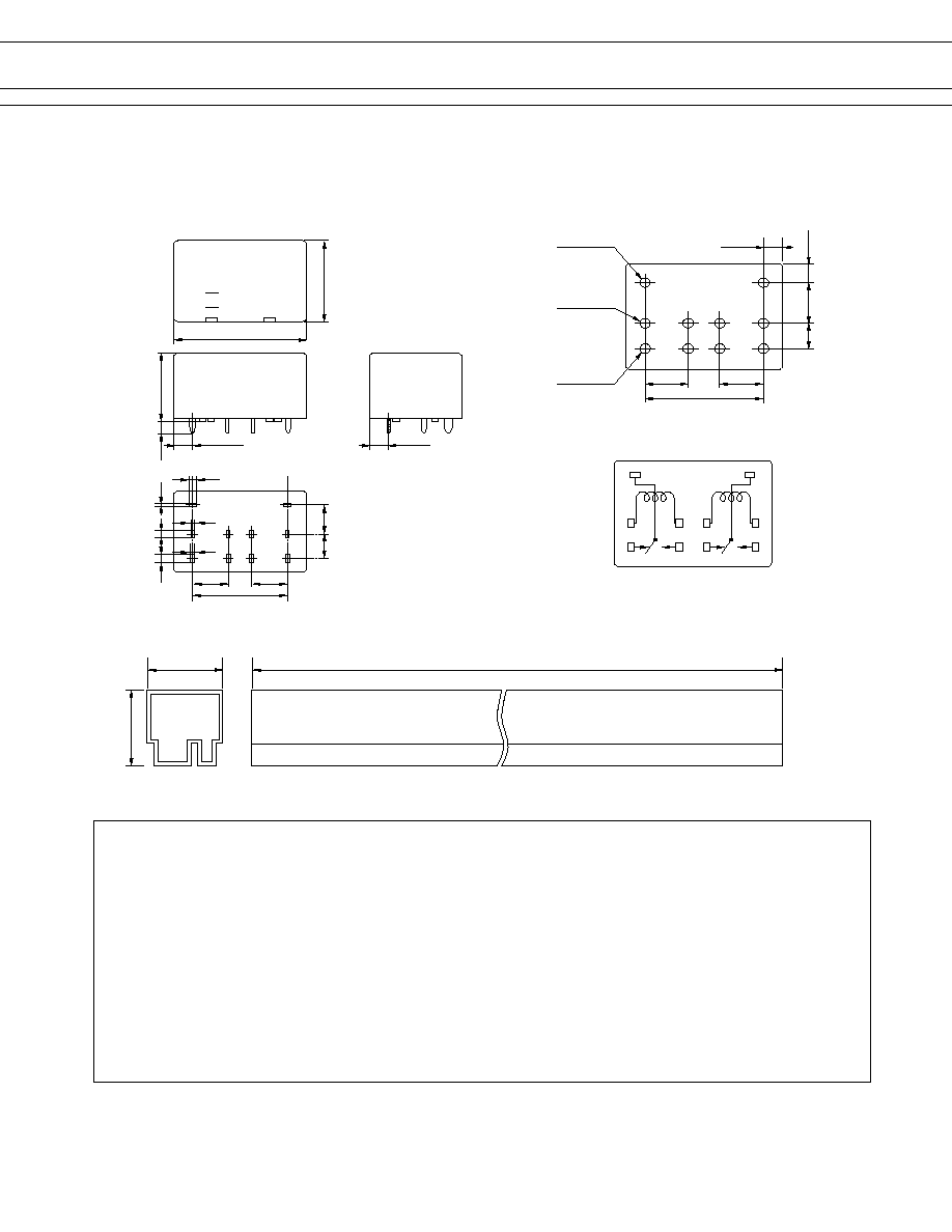
s
DIMENSIONS
Unit: mm
25.2Max
562Maximum
22.9Max
q
Tube carrier
F
562ND12-N
9112
26.0
+0.5
20.0
+0.3
q
PC board mounting hole layout (BOTTOM VIEW)
7.62
5.08
7.62
3.7
4≠¯1.3
2≠¯1.4
7.62
3.09
20.32
4≠¯1.5
9
7
8
6
10
N.C.
N.O.
q
Schematic
COM
4
2
3
1
5
COM
N.C.
N.O.
20pieces/tube
(3.09)
16.2
+0.3
3.5
(3.7)
1.2
0.3
0.5
7.62
7.62
20.32
7.62
5.08
1.0
0.3
1.2
II
I
(BOTTOM VIEW)
q
Dimensions
© 2003 Fujitsu Components America, Inc. All company and product names are trademarks or registered trademarks
of their respective owners. Rev. 02/18/2003
Japan
Fujitsu Component Limited
Gotanda-Chuo Building
3-5, Higashigotanda 2-chome, Shinagawa-ku
Tokyo 141, Japan
Tel: (81-3) 5449-7010
Fax: (81-3) 5449-2626
Email: promothq@ft.ed.fujitsu.com
Web: www.fcl.fujitsu.com
North and South America
Fujitsu Components America, Inc.
250 E. Caribbean Drive
Sunnyvale, CA 94089 U.S.A.
Tel: (1-408) 745-4900
Fax: (1-408) 745-4970
Email: marcom@fcai.fujitsu.com
Web: www.fcai.fujitsu.com
Europe
Fujitsu Components Europe B.V.
Diamantlaan 25
2132 WV Hoofddorp
Netherlands
Tel: (31-23) 5560910
Fax: (31-23) 5560950
Email: info@fceu.fujitsu.com
Web: www.fceu.fujitsu.com
Asia Pacific
Fujitsu Components Asia Ltd.
102E Pasir Panjang Road
#04-01 Citilink Warehouse Complex
Singapore 118529
Tel: (65) 6375-8560
Fax: (65) 6273-3021
Email: fcal@fcal.fujitsu.com
www.fcal.fujitsu.com
Fujitsu Components
International
Headquarter
Offices