 | –≠–ª–µ–∫—Ç—Ä–æ–Ω–Ω—ã–π –∫–æ–º–ø–æ–Ω–µ–Ω—Ç: FBR56Ns-W | –°–∫–∞—á–∞—Ç—å:  PDF PDF  ZIP ZIP |
s
FEATURES
q
High power contact capacity
(carrying current: 40 A/2 minutes, 30 A/1 hour)
q
High heat resistance and extended operating voltage
s
ORDERING INFORMATION
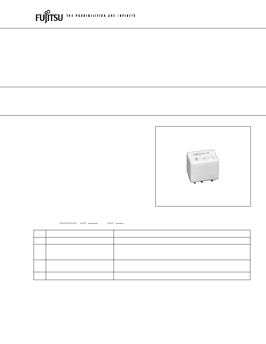
FBR56 SERIES
COMPACT HIGH POWER RELAY
1 POLE--30 A
(FOR AUTOMOTIVE APPLICATIONS)
(a)
Series Name
FBR56 : FBR56 Series relay for 12 V battery (contact gap 0.4 mm)
(b)
Enclosure
N
: Plastic sealed type
(c)
Nominal Voltage
D06
: 6 VDC
D09
: 9 VDC
D12
: 12 VDC
(d)
Contact Material
W
: Silver-tin oxide indium
N
: Silver copper nickel
(e)
Custom Designation
To be assigned custom specification
FBR56
N
D12
≠
W
**
[Example]
(a)
(b)
(c)
(d)
(e)
1
2
FBR56 SERIES
s
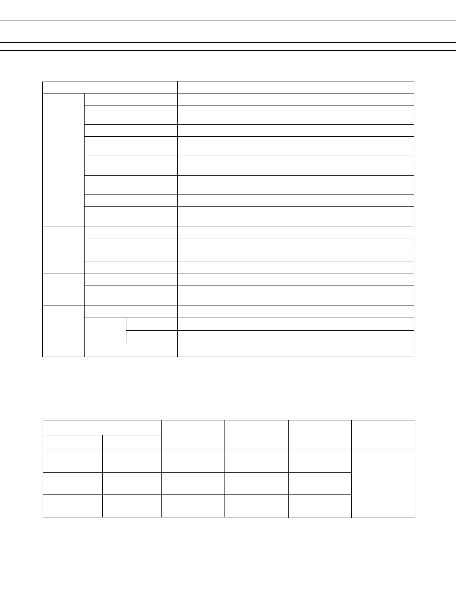
COIL DATA CHART
MODEL
Nominal
Coil
Must operate
Thermal
voltage
resistance
voltage
resistance
W contact
N contact
(
±
10%) (at 20
∞
C)
FBR56ND06-W
FBR56ND06-N
6 VDC
42
3.6 VDC (at 20
∞
C)
4.5 VDC (at 85
∞
C)
FBR56ND09-W
FBR56ND09-N
9 VDC
95
5.4 VDC (at 20
∞
C)
77
∞
C/W
6.8 VDC (at 85
∞
C)
FBR56ND12-W
FBR56ND12-N
12 VDC
170
7.3 VDC (at 20
∞
C)
9.2 VDC (at 85
∞
C)
s
SPECIFICATIONS
Item
Specifications
Contact
Arrangement
1 form C
Material
Silver-tin oxide indium (≠W type)
Silver copper nickel (≠N type)
Voltage Drop (resistance)
Maximum 100 mV (at 2 A 12 VDC)
Ratings
14 VDC 20 A (locked motor load)
14 VDC inrush 20 A, break 4 A (motor free load)
Maximum Carrying Current
40 A/2 minutes, 30 A/1 hour
(25
∞
C, 100% rated coil voltage)
Maximum Inrush Current
≠W type: 60 A (reference)
≠N type: 40 A
Maximum Switching Current
40 A 16 VDC (reference)
Minimum Switching Load*
1
≠W type: 6 VDC, 1 A
≠N type: 6 VDC, 2 A (reference)
Coil
Operating Temperature
≠40
∞
C to +85
∞
C (no frost) (refer to the CHARACTERISTIC DATA)
Storage Temperature
≠40
∞
C to +100
∞
C (no frost)
Time Value
Operate (at nominal voltage)
Maximum 10 ms
Release (at nominal voltage)
Maximum 5 ms
Life
Mechanical
10
◊
10
6
operations minimum
Electrical
100
◊
10
3
operations minimum (locked motor load)
1
◊
10
6
operations minimum (motor free load)
Other
Vibration Resistance
10 to 55 Hz (double amplitude of 1.5 mm)
Shock Misoperation
100 m/s
2
Resistance
Endurance
1,000 m/s
2
Weight
Approximately 9.4 g
*1 Values when switching a resistive load at normal room temperature and humidity, and in a clean environment.
The minimum switching load varies with the switching frequency and operating environment.
3
FBR56 SERIES
s
PRINCIPAL APPLICATIONS
Application
Normal load current
Life x 10
3
Recommended
model (Example)
Power Windows
20 to 30 A (switching at motor locking)
100
FBR56N
s
s
-W
Automatic Door Lock
18 to 30 A/4 to 5 door (switching at motor locking)
100
FBR56N
s
s
-W
Intermittent Wipers
INRUSH 15 to 30 A
300
FBR56N
s
s
-N
For 12 V
BREAK 2 to 8 A (motor free)
battery
Tilt-Lock Wheel
INRUSH 15 A
100
FBR56N
s
s
-W
BREAK 2.5 A (motor free)
Sunroof
20 to 30 A (switching at motor locking)
100
FBR56N
s
s
-W
Others
Car audio system, etc.
--
FBR56N
s
s
-W
s
CHARACTERISTIC DATA
1. MAXIMUM BREAK CAPACITY
2. LIFE
Locked motor load
Resistive load
Contact switching current (A)
Voltage between contacts (VDC)
10
15
20
25
30
40
50
50
20
15
12
10
5
1
8 10
12
15
20
30
40
50
Locked motor current (A)
Number of operations (x10
4
)
30
20
10
5
3
14 VDC

4
FBR56 SERIES
3. LIFE TEST (EXAMPLE)
(Continued)
∑ Shift of pick-up and drop-out voltage
Ratio of pick-up and
drop-out values
to rated coil voltage
0
100
10
1
20
40
60
80
100
∑ Test item
14 V DC-20 A
Motor lock
200,000 operations minimum
(FBR56 -W type)
∑ Current wave form
∑ Test circuit
(RL-1)
20 sec
20 A
0 A
20 A
0 A
(RL-2)
0.3 sec
10 sec
0.3 sec
∑ Shift of contact resistance
100
10
1
1000
100
10
(measured at 6 V-1 A)
M
RL-1
RL-2
N.O.
N.C.
N.O.
N.C.
PICK-UP
DROP-OUT
Contact resistance
No. of operations (x10
4
)
Initial
Initial
∑ Shift of pick-up and drop-out voltage
Ratio of pick-up and
drop-out values
to rated coil voltage
0
100
10
1
20
40
60
80
100
∑ Test item
14 V DC-30 A
Motor lock
100,000 operations minimum
(FBR56 -W type)
∑ Current wave form
∑ Test circuit
(RL-1)
20 sec
30 A
0 A
0 A
(RL-2)
0.3 sec
10 sec
0.3 sec
∑ Shift of contact resistance
100
10
1
1000
100
10
(measured at 6 V-1 A)
M
RL-1
RL-2
N.O.
N.C.
N.O.
N.C.
PICK-UP
DROP-OUT
Contact resistance
No. of operations (x10
4
)
Initial
Initial
5
FBR56 SERIES
(Continued)
∑ Shift of pick-up and drop-out voltage
Ratio of pick-up and
drop-out values
to rated coil voltage
0
100
10
1
20
40
60
80
100
∑ Test item
16 V DC-25 A INRUSH
Motor free
400,000 operations minimum
(FBR56 -N type)
∑ Current wave form
∑ Test circuit
∑ Shift of contact resistance
100
10
1
1000
100
10
(measured at 6 V-1 A)
M
N.O.
N.C.
PICK-UP
DROP-OUT
Contact resistance
No. of operations (x10
4
)
Initial
Initial
4 A
16 A
0 A
25 A
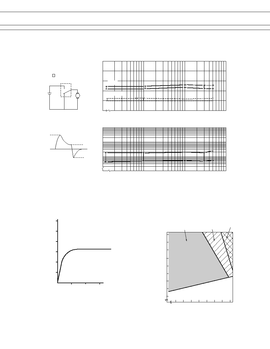
4. COIL TEMPERATURE RISE
5. OPERATING COIL VOLTAGE RANGE (EXAMPLE)
Coil temperature rise (
∞C
)
120
100
80
60
40
20
0
0
10
12
30
Applied time (minutes)
0.8 W
Ratio of operating
voltage to rated
coil voltage (%)
133
130
120
110
100
90
80
70
60
50
10
20
30
40
50
60
70
80 85
Operating temperature (∞C)
Operating voltage
Continuous at carrying
current of 20 A
Within 5 minutes
at carrying current
of 20 A
Within 3 minutes
at carrying current
of 20 A
6
FBR56 SERIES
6. VIBRATION RESISTANCE CHARACTERISTICS
Dual amplitude
Frequency (Hz)
Acceleration
(G)
4.4 G
10
1
Automotive
electronics
standard
10
50
100
200
600
1000
2000
5
1
0.5
0.1
0.01
X
Y
Z
FBR56
Range where chattering occurs
N.O.contact
coil not energized
on X-direction
7. SHOCK RESISTANCE CHARACTERISTICS
X1
Y2
Z1
FBR56
Y1
Z2
X2
Shock direction
X1
X2
Y2
Z1
Z2
Y1
100
80
60
40
20
0
Shock
level
(G)
: N.C. contact (coil de-energized)
: N.O. contact (coil energized)
7
FBR56 SERIES
s
REFERENCE DATA
80
60
40
20
0 10 20 30 40 50 60 70 80
0
Distribution (%)
FBR56
n = 100
Operate
Release
Distribution of operate and release voltage
Nominal voltage multiplying factor (%)
80
100
60
40
20
0
1 2
3
4
5
6
7
8
0
FBR56
n = 100
Operate
Release
Distribution of operate and release time
Time (ms)
0 10 20 30 40 50 60 70 80
100
80
60
40
20
0
FBR56
n = 100
Distribution of contact resistance
Contact resistance (m
)
Distribution (%)
Distribution (%)
s
DIMENSIONS
7.62
(3.4)
3.5
16.2
+0.3
F
56D12-N
9415A
20.0
+0.3
14.4
+0.3
35 pcs/tube
25.2 Max.
562 Max.
22.9 Max.
q
Tube carrier
Terminal No.1, 2
0.5
t
x1.2
W
Terminal No.3, 4
0.3
t
x1.0
W
Terminal No.5, 6
0.3
t
x 1.2
W
(3.9)
7.62
5.08
Unit : mm
4
2
3
1
6
5
COM.
N.O.
N.C.
q
Dimensions
q
PC board mounting hole layout
(BOTTOM VIEW)
q
Schematics (BOTTOM VIEW)
7.62
5.08
7.62
3.9
2-¯
1.5
2-¯1.3
2-¯ 1.4

8
FBR56 SERIES
© 2003 Fujitsu Components America, Inc. All company and product names are trademarks or registered trademarks
of their respective owners. Rev. 02/18/2003
Japan
Fujitsu Component Limited
Gotanda-Chuo Building
3-5, Higashigotanda 2-chome, Shinagawa-ku
Tokyo 141, Japan
Tel: (81-3) 5449-7010
Fax: (81-3) 5449-2626
Email: promothq@ft.ed.fujitsu.com
Web: www.fcl.fujitsu.com
North and South America
Fujitsu Components America, Inc.
250 E. Caribbean Drive
Sunnyvale, CA 94089 U.S.A.
Tel: (1-408) 745-4900
Fax: (1-408) 745-4970
Email: marcom@fcai.fujitsu.com
Web: www.fcai.fujitsu.com
Europe
Fujitsu Components Europe B.V.
Diamantlaan 25
2132 WV Hoofddorp
Netherlands
Tel: (31-23) 5560910
Fax: (31-23) 5560950
Email: info@fceu.fujitsu.com
Web: www.fceu.fujitsu.com
Asia Pacific
Fujitsu Components Asia Ltd.
102E Pasir Panjang Road
#04-01 Citilink Warehouse Complex
Singapore 118529
Tel: (65) 6375-8560
Fax: (65) 6273-3021
Email: fcal@fcal.fujitsu.com
www.fcal.fujitsu.com
Fujitsu Components
International
Headquarter
Offices