s
FEATURES
q
High power contact capacity
(carrying current: 40 A/2 minutes, 30 A/1 hour)
q
Suitable for controlling 24 V motors in trucks and other
large vehicles
q
High heat resistance and extended operating voltage
s
ORDERING INFORMATION
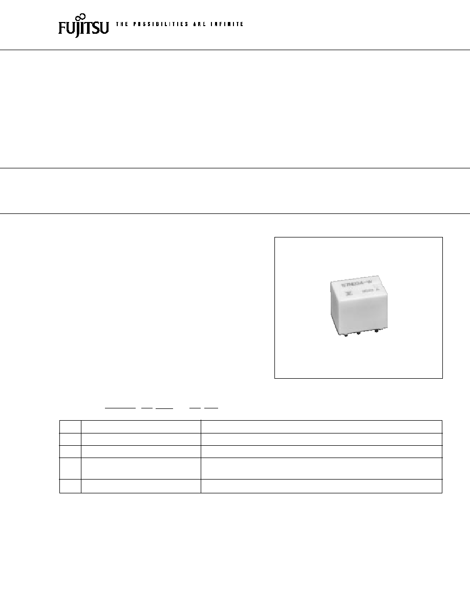
FBR57 SERIES
COMPACT HIGH POWER RELAY
1 POLE--12 A (28 VDC)
(FOR 24 V BATTERY AUTOMOTIVE
APPLICATIONS)
(a)
Series Name
FBR57 : FBR57 Series relay for 24 V battery (contact gap 0.8 mm)
(b)
Enclosure
N
: Plastic sealed type
(c)
Nominal Voltage
D24
: 24 VDC
(d)
Contact Material
W
: Silver-tin oxide indium
N
: Silver copper nickel
(e)
Custom Designation
To be assigned custom specification
FBR57
N
D24
�
W
**
[Example]
(a)
(b)
(c)
(d)
(e)
1
2
FBR57 SERIES
s
COIL DATA CHART
s
SPECIFICATIONS
Item
Specifications
Contact
Arrangement
1 form C
Material
Silver-tin oxide indium (�W type)
Silver copper nickel (�N type)
Voltage Drop (resistance)
Maximum 100 mV (at 2 A 12 VDC)
Ratings
28 VDC 12 A (locked motor load)
28 VDC inrush 15 A, break 2.5 A (motor free load)
Maximum Carrying Current
40 A/2 minutes, 30 A/1 hour
(25
�
C, 100% rated coil voltage)
Maximum Inrush Current
�W type: 60 A (reference)
�N Type: 40 A
Maximum Switching Current
12 A 28 VDC (reference)
Minimum Switching Load*
1
�W type: 6 VDC, 1 A
�N type: 6 VDC, 2 A (reference)
Coil
Operating Temperature
�40
�
C to +85
�
C (no frost) (refer to the CHARACTERISTIC DATA)
Storage Temperature
�40
�
C to +100
�
C (no frost)
Time Value
Operate (at nominal voltage)
Maximum 10 ms
Release (at nominal voltage)
Maximum 5 ms
Life
Mechanical
1
�
10
6
operations minimum
Electrical
1
�
10
5
operations minimum (locked motor load)
5
�
10
5
operations minimum (motor free load)
Other
Vibration Resistance
10 to 55 Hz (double amplitude of 1.5 mm)
Shock Misoperation
100 m/s
2
Resistance
Endurance
1,000 m/s
2
Weight
Approximately 9.4 g
*1 Values when switching a resistive load at normal room temperature and humidity, and in a clean environment.
The minimum switching load varies with the switching frequency and operating environment.
MODEL
Nominal
Coil
Must operate
Thermal
voltage
resistance
voltage
resistance
W contact
N contact
(
�
10%) (at 20
�
C)
FBR57ND24-W
FBR57ND24-N
24 VDC
384
14.4 VDC (at 20
�
C)
67
�
C/W
18.0 VDC (at 85
�
C)
3
FBR57 SERIES
s
PRINCIPAL APPLICATIONS
Application
Normal load current
Life x 10
3
Recommended
model (example)
Power Windows
10 to 12 A (switching at motor locking)
100
FBR57N
s
s
-W
For 24 V
Automatic Door Lock
5 A/2 door (switching at motor locking)
100
FBR57N
s
s
-W
battery
Intermittent Wipers
INRUSH 15 to 30 A
300
FBR57N
s
s
-N
BREAK 2 to 8 (motor free)
s
CHARACTERISTIC DATA
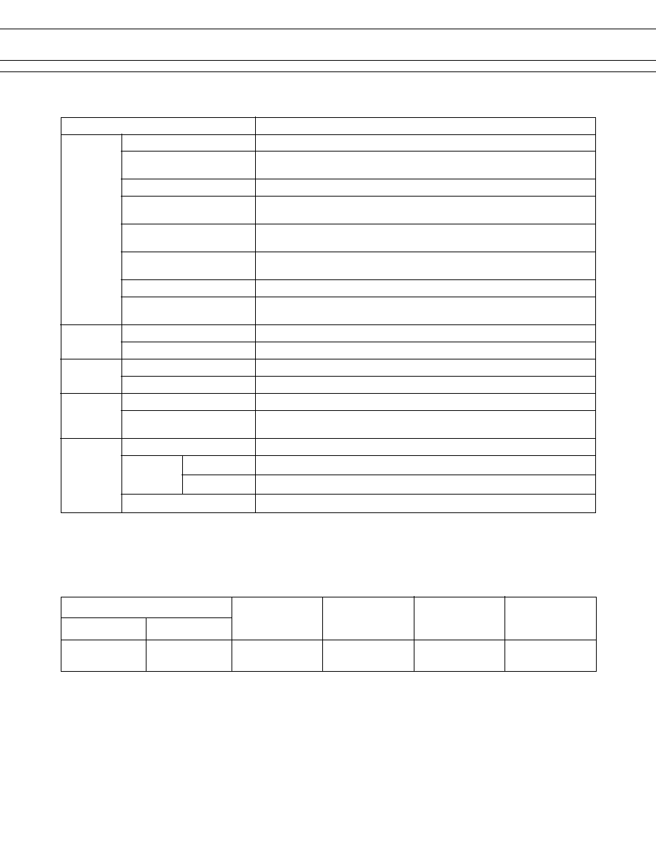
1. MAXIMUM BREAK CAPACITY
2. LIFE
Locked motor load
Resistive load
Contact switching current (A)
Voltage between contacts (VDC)
10
15
20
25
30
40
50
50
20
15
12
10
5
1
8 10
12
15
20
30
Locked motor current (A)
Number of operations (x10
4
)
30
20
10
5
3
28 VDC
4
FBR57 SERIES
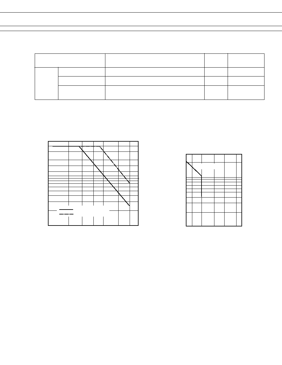
3. LIFE TEST (EXAMPLE)
� Shift of pick-up and drop-out voltage
Ratio of pick-up and
drop-out values
to rated coil voltage
0
100
10
1
20
40
60
80
100
� Test item
28 V DC-12 A INRUSH
Motor lock
100,000 operations minimum
(FBR57 -W type)
� Current wave form
� Test circuit
(RL-1)
20 sec
12 A
0 A
0 A
(RL-2)
0.3 sec
10 sec
0.3 sec
� Shift of contact resistance
100
10
1
1000
100
10
(measured at 6 V-1 A)
M
RL-1
RL-2
N.O.
N.C.
N.O.
N.C.
PICK-UP
DROP-OUT
Contact resistance
No. of operations (x10
4
)
Initial
Initial
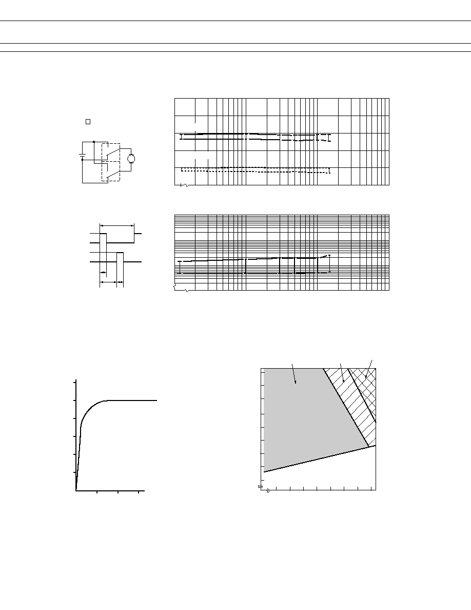
4. COIL TEMPERATURE RISE
5. OPERATING COIL VOLTAGE RANGE (EXAMPLE)
Coil temperature rise (
�C
)
120
100
80
60
40
20
0
0
10
12
30
Applied time (minutes)
Carring current : 20 A
Ratio of operating
voltage to rated
coil voltage (%)
133
130
120
110
100
90
80
70
60
50
10
20
30
40
50
60
70
80 85
Operating temperature (�C)
Operating voltage
Continuous at carrying
current of 20 A
Within 5 minutes
at carrying current
of 20 A
Within 3 minutes
at carrying current
of 20 A
5
FBR57 SERIES
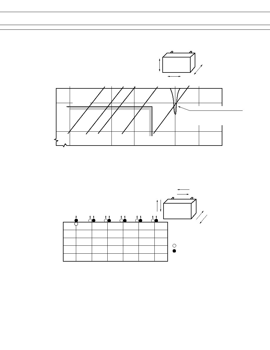
6. VIBRATION RESISTANCE CHARACTERISTICS
7. SHOCK RESISTANCE CHARACTERISTICS
Dual amplitude
Frequency (Hz)
Acceleration
(G)
4.4 G
10
1
Automotive
electronics
standard
10
50
100
200
600
1000
2000
5
1
0.5
0.1
0.01
X
Y
Z
FBR57
Range where chattering occurs
N.O.contact
coil not energized
on X-direction
X1
Y2
Z1
FBR57
Y1
Z2
X2
Shock direction
X1
X2
Y2
Z1
Z2
Y1
100
80
60
40
20
0
Shock
level
(G)
: N.C. contact (coil de-energized)
: N.O. contact (coil energized)