
s
FEATURES
∑ 1.27 mm (0.050 in.) pitch contact arrangement in two
rows enables high-density mounting.
∑ Connectors are available with 30 to 120 contacts.
∑ Terminals are spaced in a four-row staggered
arrangement (2.54 mm (0.100 in.)
◊
1.905 mm (0.075
in.)) for easy PC board design.
∑ Sockets are available for board mounting and for flat
cables.
[See the description of the FCN-210 series (for board-
to-cable connection).]
∑ Insulation is UL-approved (94V-0) and is washable.
s
MATERIALS
Item
Insulator
Conductor
Plating
Materials
Polyester (UL94V-0)
Copper alloy
Contact
Terminal
Gold plating
Palladium plating
s
SPECIFICATIONS
Item
Operating temperature
range
Current rating
Voltage rating
Contact resistance
Insulation resistance
Dielectric withstand
voltage
Insertion force
Withdrawal force
Applicable PC board
(standard)
Specifications
≠55
∞
C to +105
∞
C
DC 2 A
AC 250 V
35 m
max. (DC 6 V, 0.1 V)
1000 M
min. (DC 500 V)
500 VAC for 1 minute
4 kg max. (10 pins)
250 g min. (10 pins)
Thickness: 0.8 to 1.6 mm
(0.031 to 0.063 in.)
FUJITSU TAKAMISAWA
COMPONENT CATALOG
FOR BOARD-TO-BOARD CONNECTION
210 SERIES
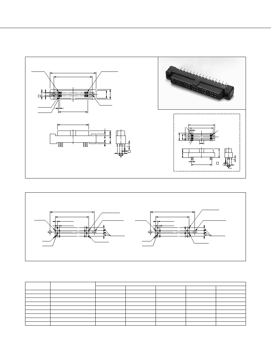
210 Series
2
-30, 34 and 50 contacts
No. 2
Bump side
End terminal
(Mounting hole)
No. 1
No. 3
-40, 60, 80, 92, 100 and 120 contacts
No. 2
Bump side
End terminal
(Mounting hole)
No. 1
No. 3
Unit: mm (in.)
(Component side)
C
±
0.1 (
±
0.004)
B
±
0.1 (
±
0.004)
1.27
±
0.1
(.050
±
0.004
)
1.27
±
0.1
(.050
±
0.004
)
1.905
±
0.01
(.075
±
0.004
)
2-
2.2
-0
(.087
-0
)
+0.2
+0.008
0.8
±
0.06
(.031
±
0.002
)
0.8
±
0.06
(.031
±
0.002
)
C
±
0.1 (
±
0.004)
B
±
0.1 (
±
0.004)
1.27
±
0.1
(.050
±
0.004
)
1.27
±
0.1
(.050
±
0.004
)
1.905
±
0.01
(.075
±
0.004
)
2-
2.2
-0
(.087
-0
)
+0.2
+0.008
A
B
3.2 (0.126)
7.6
(0.299)
5.9 (0.232)
No.2
End terminal
2-
2.2
(0.086)
C
No.1
No.3
D
5.2
(0.204)
5.2
(0.204)
1.5 (0.006)
5 (0.196)
5 (0.196)
0.55
(0.021)
2.8 (0.110)
2.8 (0.110)
1.905
(0.075)
1.905
(0.075)
0.4
(0.016)
0.4
(0.016)
A
B
8
No. 2
End terminal
4
C
10.2
(0.401)
5.9
No. 1
No. 3
(No-mounting-flange type)
Unit: mm (in.)
2.54
(0.100)
1.27
(0.050)
2.54
(0.100)
1.27
(0.050)
1.27
(0.050)
STRAIGHT SOCKET
s
DIMENSIONS
s
MOUNTING HOLE LAYOUT
The no-mounting-flange type does not require the mounting hole of 2-
2.2 mm (0.09 in.).
s
PART NUMBERS AND DIMENSIONS
Number of
contacts
30
34
40
50
60
80
92
100
120
Part number
FCN-214J030-G/0
FCN-214J034-G/0
FCN-214J040-G/0
FCN-214J050-G/0
FCN-214J060-G/0
FCN-214J080-G/0
FCN-214J092-G/0
FCN-214J100-G/0
FCN-214J120-G/0
A
31.83 (1.253)
34.73 (1.367)
38.18 (1.503)
44.35 (1.746)
50.88 (2.003)
63.58 (2.503)
71.20 (2.803)
76.28 (3.003)
88.98 (3.503)
Dimensions (mm (in.))
Replace "-G/0" with "-G/A" for no-mounting-flange type
B
26.28 (1.035)
28.82 (1.135)
32.63 (1.285)
38.98 (1.535)
45.33 (1.785)
58.03 (2.285)
65.65 (2.585)
70.73 (2.785)
83.43 (3.285)
C
17.78 (0.700)
20.32 (0.800)
24.13 (0.950)
30.48 (1.200)
36.83 (1.450)
49.53 (1.950)
57.15 (2.250)
62.23 (2.450)
74.93 (2.950)
D
20.68 (0.814)
23.22 (0.914)
27.03 (1.064)
33.38 (1.314)
39.73 (1.564)
52.43 (2.064)
60.05 (2.364)
65.13 (2.564)
77.83 (3.064)
E
23.08 (0.909)
25.62 (1.009)
29.43 (1.159)
35.78 (1.409)
42.13 (1.659)
54.83 (2.159)
62.45 (2.459)
67.53 (2.659)
80.23 (3.159)