FLD5F6CX-J
Edition 1.0
December 1999
1
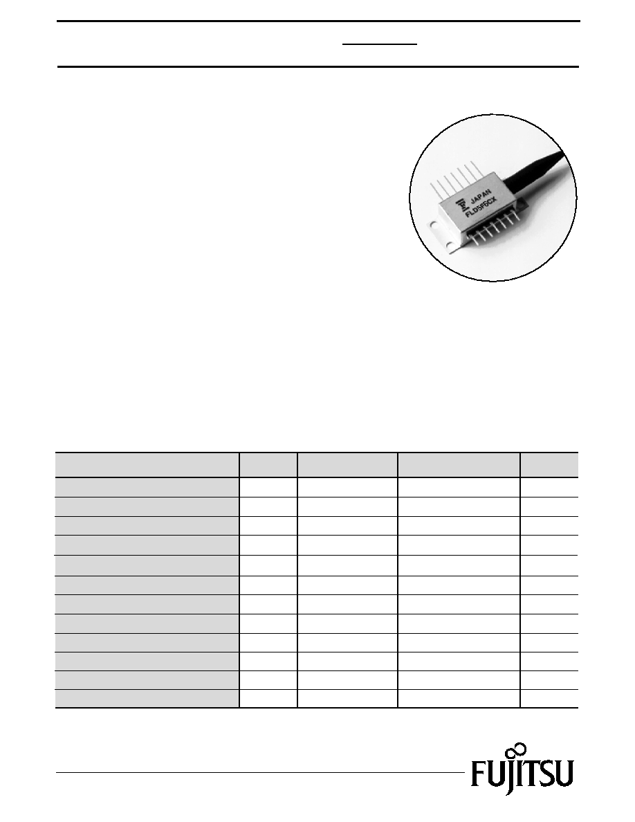
1,550nm MQW-DFB
DWDM Direct Modulation Laser
FLD5F6CX-J
FEATURES
· Direct Modulated MQW DFB Laser
· Built-in TEC, Thermistor and Monitor PD
· 14-Pin Butterfly Type Module
· 10mW Output Power
· Low Residual Chirp
· Optimized for 2.5 Gb/s Modulation Rates
· Selected wavelengths according to ITU-T grid available
APPLICATIONS
This MQW laser is intended for the application of 2.5 Gb/s
long haul Dense Wavelength Division Multiplexing (DWDM).
Transmission spans of 100 km are possible without amplification.
DESCRIPTION
The Multiple Quantum Well (MQW) Laser is a high power laser
capable of 2.5 Gb/s transmission. It is packaged in a "butterfly" type module.
The module employs a high efficiency optical coupling system, coupling the
laser output through a built-in optical isolator into a single mode fiber pigtail.
The modules also include a monitor photodiode, a thermoelectric cooler (TEC)
and thermistor. This device is designed for use in DWDM direct modulation transmission
systems. Selected wavelengths specified to the ITU-T grid are available.
Parameter
Forward Current
TEC Voltage
Symbol
Condition
IF
Photodiode Reverse Voltage
VDR
Vc
150
10
2.5
Ratings
mA
Photodiode Forward Current
IDF
20
V
V
Optical Output Power
Pf
12.0
CW
CW
<260
°C
mW
mA
Reverse Voltage
VR
2
V
Unit
ABSOLUTE MAXIMUM RATINGS (Tc=25°C)
TEC Current
Lead Soldering Time
Ic
Tsold
1.4
10
95
95
A
sec
Environmental Operating Humidity
Environmental Storage Humidity
Xop
%
%
Storage Temperature
Tstg
-40 to +70
-
-
-
-
-
-
-
°C
Operating Case Temperature
Top
-20 to +65
°C
Xst
Top<30
°C
Tst<30
°C

1,550nm MQW-DFB
DWDM Direct Modualtion Laser
FLD5F6CX-J
2
Parameter
Threshold Power
Symbol
Pth
Slope Efficiency
Series Resistance
Rs
Optical Output Power
Pf
OPTICAL AND ELECTRICAL CHARACTERISTICS (TL=Tset, Tc=25°C, BOL, unless otherwise specified)
Laser Set Temperature
Tset
Tracking Error (Note 1)
TE
IF=Ith, CW
Conditions
CW, Pf=10mW
CW
-
Pf=10mW, Tc=-20 to 65°C
µW
mW/mA
mW
Unit
°C
22
Min.
20
Limits
28
-
-
150
10.0
0.14
-
dB
+0.5
-0.5
Kinks (up to 2.4 mW)
Kns
-
None
BER Performance
ER
Note (3)
No Floor
Pulsation
-
-
None
Peak Wavelength
p
Note (2)
Note (4)
nm
35
Threshold Current
Ith
CW
mA
3
40
Forward Voltage
VFDC
CW, IF=30 mA, pin 12-13
CW, pin 12-13
V
-
25
-
-
-
-
Monitor Current
Im
CW, Pf=10mW, VDR=5V
mA
1.0
0.10
-
-
Photodiode Dark Current
ID
VDR=5V
nA
100
-
2
Photodiode Capacitance
Ct
VDR=5V, f=1 MHz
pF
10
-
-
Photodiode Cutoff Frequency
fcm
VDR=5V, 50 load
MHz
-
100
-
Side Mode Suppression
Sr
Note (2)
dB
-
33
35
Rise Time (10%-90%)
tr
Note (2)
nsec
0.125
-
0.1
Spectral Width (-20dB)
-
Note (2)
nm
0.5
-
-
Fall Time (10%-90%)
tf
Note (2)
nsec
0.125
-
0.1
Cutoff Frequency
fc
Pf=10mW, -3 dB
GHz
-
4.0
-
Relative Intensity Noise
RIN
f=2.5 GHz
Pf=10 mW, ORL=24 dB
dB/Hz
-140
-
-
dB
Power Penalty
PP
Note (3)
1.5
-
-
In-Band Ripple (Window)
S21
f=50 MHz~3 GHz
f=50 MHz~2 GHz
dB
dB
+/-1.5
-
8
-
-
-
RF Return Loss
S11
f=2 GHz~3 GHz
f=3 GHz~5 GHz
dB
dB
6
-
3
-
-
-
Optical Isolation
Is
Tc=-20 to 65
°C
dB
-
25
35
-
1.6
1.75
Max.
Typ.
Note 1. TE=10*log{pf(Tcase)/Pf(Tc=25
°C)}dB, APC
Note 2. 2.5 Gb/s NRZ, pseudo-random, Pb=0.2mW, Ppeak=2.0mW
Note 3. Bit rate=2.48832 Gb/s, PRBS=2
23
-1, Dispersion=1,800 ps/nm (116km), Ppeak=10mW,
Pbias=1.0mW (Extinction ratio=10dB), B.E.R.=1x10
--10
Decision point: Center of Back-to-Back at 10Decision point: Center of Back-to-Back at 10
-9
,
Receiver: Fujitsu Standard Receiver
Note 4. The selected wavelengths available are listed in Fig. 8
3
1,550nm MQW-DFB
DWDM Direct Modulation Laser
FLD5F6CX-J
Parameter
TEC Current
TEC Voltage
Cooler Power
Thermistor Resistance
Thermistor B Constant
Symbol
Ic
Vc
Rtr
B
TL=Tset,
Pf=10mW, Tc=65
°C
TL=Tset,
Pf=10mW, Tc=65
°C
TL=Tset,
Pf=10mW, Tc=65
°C
TL=Tset,
Pf=10mW, Tc=65
°C
TL=15 to 35
°C
-
Test Conditions
A
V
W
K
k
Unit
TEC Resistance
RTEC
PTEC
TEC AND THERMISTOR CHARACTERISTICS
Limit
1.0
2.4
2.4
12.6
Max.
Typ.
-
-
-
7.7
3.2
-
-
-
-
3,630
3,270
3,450
2.4
2.0
Min.
(TL=Tset, Tc=25°C, BOL, unless otherwise specified)
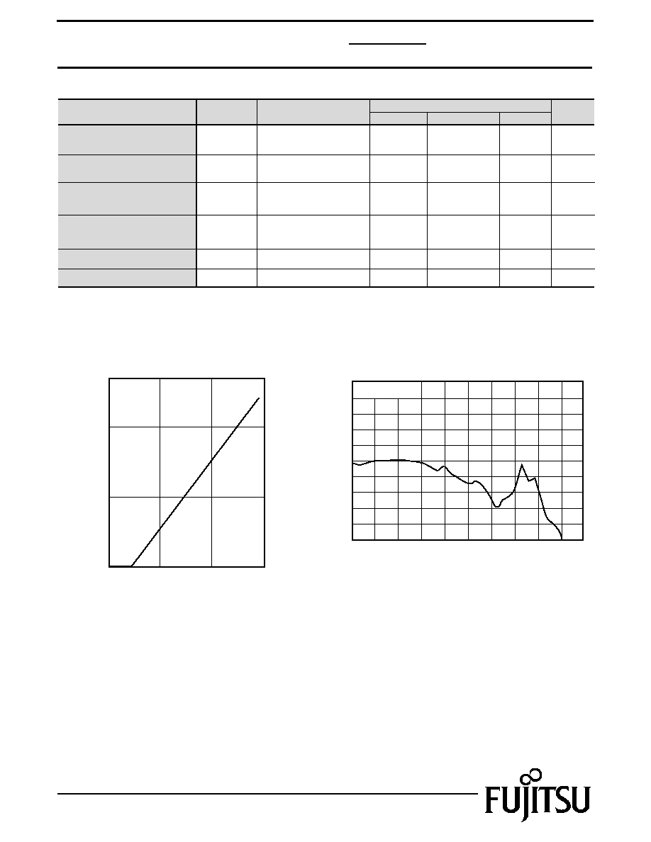
Fig. 1 Forward Current vs Output Power
Forward Current, If (mA)
Output Power, Pf (mW)
0
5
10
0
30
60
90
Fig. 2 Frequency Response
Frequency (GHz)
Relative Output (dB)
6
3
0
-3
-6
-9
-12
9
12
0
2
4
6
8
10
Pf=10mW
TL = 25°C
4
1,550nm MQW-DFB
DWDM Direct Modualtion Laser
FLD5F6CX-J
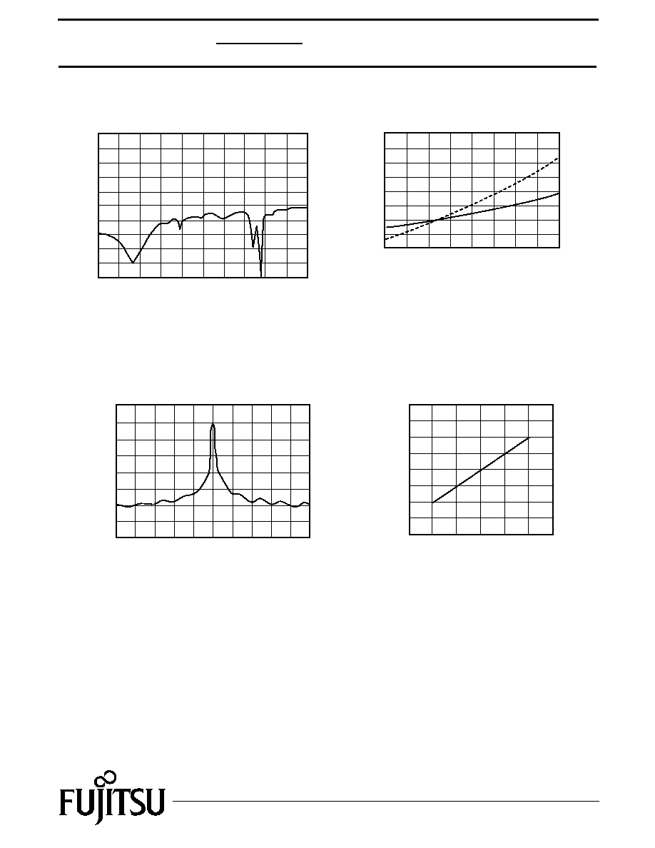
Fig. 4 Cooler Voltage -Current
Case Temperature (
°C)
Cooler Voltage (V)
Cooler Current (A)
-1.0
3.0
2.0
0.0
1.0
-1.0
3.0
2.0
0.0
1.0
0
20
30
10
40
50
60
Ic
Vc
70
80
Fig. 3 RF Return Loss
Frequency (GHz)
Return Loss (dB)
10
0
-10
-20
20
0
2
4
6
8
10
Fig. 5 Spectrum
Wavelength
(nm)
Relative Intensity (dB)
0
-10
-40
-50
-60
-20
-30
10
1545
1550
1555
Fig. 6 Temperature Dependance of
Wavelength (ACC)
Laser Temperature, TL (°C)
Wavelength (nm)
1550
1551
1552
1553
1554
10
20
30
40
5
1,550nm MQW-DFB
DWDM Direct Modulation Laser
FLD5F6CX-J
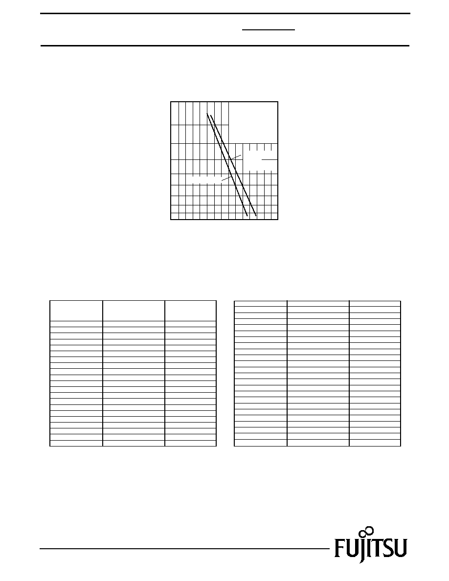
Fig. 7 Transmission Characteristics
Average Received Optical Power (dBm)
Bit Error Rate
10
-12
10
-10
10
-8
10
-6
10
-4
-40
-35
-30
-25
2.48832 Gb/s, NRZ
PRBS 2
23-1
TL=Tset,
Ppeak=10mW,
Pb=1mW,
(Rext=10dB)
After
116km
Transmission
Back to Back
Fig. 8 Wavelength Table
Part Number
FLD5F6CX-J62
-J61
-J60
-J59
-J58
-J57
-J56
-J55
-J54
-J53
-J52
-J51
-J50
-J49
-J48
-J47
1527.99
1528.77
1529.55
1530.33
1531.12
1531.90
1532.68
1533.47
1534.25
1535.04
1535.82
1536.61
1537.40
1538.19
1538.98
1539.77
1540.56
1541.35
1542.14
1542.94
1543.73
±0.1
±0.1
±0.1
±0.1
±0.1
±0.1
±0.1
±0.1
±0.1
±0.1
±0.1
±0.1
±0.1
±0.1
±0.1
±0.1
±0.1
±0.1
±0.1
±0.1
±0.1
Wavelength (nm)
(TL=Tset)
(in vacuum)
Tolerance (nm)
-J46
-J45
-J44
-J43
-J42
1544.53
1545.32
1546.12
±0.1
±0.1
±0.1
-J41
-J40
-J39
-J38
-J37
-J36
-J35
-J34
-J33
-J32
-J31
-J30
-J29
-J28
-J27
-J26
-J25
-J24
-J23
-J22
-J21
-J20
-J19
-J18
1546.92
1547.72
1548.51
1549.32
1550.12
1550.92
1551.72
1552.52
1553.33
1554.13
1554.94
1555.75
1556.55
1557.36
1558.17
1558.98
1559.79
1560.61
1561.42
1562.23
1563.05
±0.1
±0.1
±0.1
±0.1
±0.1
±0.1
±0.1
±0.1
±0.1
±0.1
±0.1
±0.1
±0.1
±0.1
±0.1
±0.1
±0.1
±0.1
±0.1
±0.1
±0.1