
1
NOT FOR NEW DESIGN
FTR-B2 Series
4 POLE (2 FORM C+ 2 FORM A) SIGNAL
RELAY FOR CENTRAL SWITCHING/
DATA TRANSMISSION
s
FEATURES
q
4 POLE MINIATURE RELAY
Mounting space of 175mm
2
with 4 pole relay, suitable for high
density mounting.
q
SAFETY STANDARD
- UL/CSA recognized
- Conforms to Bellcore specification & FCC part 68
- Conforms to IEC 60950 / UL1950 / EN60950 spacing
and high breakdown voltage
Clearance:
1.0mm
Creepage:
1.6mm
q
HIGH RELIABILITY
Bifurcated gold overlay silver alloy
q
HIGH HEAT RESISTANCE, FLAMMABILITY
Flammability grade of 94V-0 materials employed
q
AIR TIGHT CONSTRUCTION
Air tight construction allows high resistance to various
environments and to clean the relay
q
SMT VERSION
Surface mount type available on request
q
RoHS compliant since date code: 0430B8
Please see page 7 for more information
RoHS Compliant
)
a
(
e
m
a
N
s
e
i
r
e
S
2
B
-
R
T
F
)
b
(
t
n
e
m
e
g
n
a
r
r
A
t
c
a
t
n
o
C
e
l
o
h
h
g
u
o
r
h
t
-
A
m
r
o
F
2
+
C
m
r
o
F
2
:
M
T
M
S
-
A
m
r
o
F
2
+
C
m
r
o
F
2
:
N
)
c
(
e
p
y
T
li
o
C
)
W
m
0
0
4
(
d
r
a
d
n
a
t
S
:
A
)
d
(
e
g
a
t
l
o
V
l
a
n
i
m
o
N
li
o
C
C
D
V
5
.
4
:
5
.
4
C
D
V
2
1
:
2
1
0
)
e
(
l
a
i
r
e
t
a
M
t
c
a
t
n
o
C
y
o
ll
a
r
e
v
li
s
y
a
l
r
e
v
o
d
l
o
G
:
Z
)
f
(
n
o
i
t
a
n
g
i
s
e
D
m
o
t
s
u
C
s
t
c
u
d
o
r
P
d
e
z
i
m
o
t
s
u
C
r
o
f
r
e
b
m
u
N
l
a
i
c
e
p
S
Remarks: Actual marking on relay would not carry code FTR and be as below:
Ordering code
Actual marking
FTR-B2MA012Z
B2MA012Z
s
ORDERING INFORMATION
FTR-B2
M
A
012
Z ≠ **
[Example]
(a)
(b) (c)
(d) (e) (f )

2
FTR-B2 Series
NOT FOR NEW DESIGN
s
COIL DATA CHART
s
SAFETY STANDARD AND FILE NUMBERS
UL508, 1950 (File No. E63615)
C22.2 No. 14, No. 950 (File No. LR40304)
Please request when the approval markings are required on the cover.
Nominal voltage
Contact rating
0.2 A
125 VAC
4.5 to 12 VDC
1 A 30 VDC
resistive
0.3 A 110 VDC
e
c
n
a
r
a
e
l
C
e
g
a
p
e
e
r
C
s
k
r
a
m
e
R
m
m
0
.
1
s
t
c
a
t
n
o
c
-
a
li
o
c
m
m
6
.
1
s
t
c
a
t
n
o
c
-
li
o
c
V
0
5
1
:
e
g
a
t
l
o
v
g
n
i
k
r
o
w
-
e
d
i
s
t
u
o
d
n
a
e
d
i
s
n
i
y
a
l
e
r
-
"
2
"
e
e
r
g
e
d
n
o
i
t
u
ll
o
p
-
L
E
D
O
M
l
a
n
i
m
o
N
e
g
a
t
l
o
V
e
g
a
t
l
o
V
e
g
a
t
l
o
V
e
g
a
t
l
o
V
e
g
a
t
l
o
V
l
i
o
C
e
c
n
a
t
s
i
s
e
R
e
c
n
a
t
s
i
s
e
R
e
c
n
a
t
s
i
s
e
R
e
c
n
a
t
s
i
s
e
R
e
c
n
a
t
s
i
s
e
R
e
g
a
t
l
o
V
e
t
a
r
e
p
O
e
g
a
t
l
o
V
e
s
a
e
l
e
R
r
e
w
o
P
l
a
n
i
m
o
N
Z
5
.
4
A
)
(
2
B
-
R
T
F
C
D
V
5
.
4
0
5
C
D
V
8
3
.
3
C
D
V
5
4
.
0
w
m
0
0
4
Z
2
1
0
A
)
(
2
B
-
R
T
F
C
D
V
2
1
5
5
3
C
D
V
0
.
9
C
D
V
2
.
1
w
m
0
0
4

3
FTR-B2 Series
NOT FOR NEW DESIGN
s
SPECIFICATIONS
m
e
t
I
s
e
i
r
e
S
2
B
-
R
T
F
t
c
a
t
n
o
C
t
n
e
m
e
g
n
a
r
r
A
A
m
r
o
F
2
+
C
m
r
o
F
2
l
a
i
r
e
t
a
M
y
o
ll
a
r
e
v
li
S
y
a
l
r
e
v
o
d
l
o
G
)
l
a
i
t
i
n
i
(
e
c
n
a
t
s
i
s
e
R
m
5
7
m
u
m
i
x
a
M
)
C
D
V
6
A
1
t
a
(
)
e
v
i
t
s
i
s
e
r
(
g
n
i
t
a
R
A
2
.
0
C
A
V
5
2
1
/
A
1
C
D
V
0
3
r
e
w
o
P
g
n
i
h
c
t
i
w
S
m
u
m
i
x
a
M
A
V
5
2
/
W
0
3
e
g
a
t
l
o
V
g
n
i
h
c
t
i
w
S
m
u
m
i
x
a
M
C
A
V
5
2
1
/
C
D
V
0
1
1
t
n
e
r
r
u
C
g
n
i
h
c
t
i
w
S
m
u
m
i
x
a
M
A
1
t
n
e
r
r
u
C
g
n
i
y
r
r
a
C
m
u
m
i
x
a
M
A
5
2
.
1
e
u
l
a
V
e
m
i
T
e
m
i
T
e
t
a
r
e
p
O
)
e
g
a
t
l
o
v
l
a
n
i
m
o
n
t
a
(
s
m
0
1
m
u
m
i
x
a
M
(
e
m
i
T
e
s
a
e
l
e
R
)
e
g
a
t
l
o
v
l
a
n
i
m
o
n
t
a
s
m
5
m
u
m
i
x
a
M
li
o
C
e
r
u
t
a
r
e
p
m
e
T
g
n
i
t
a
r
e
p
O
)
t
s
o
r
f
o
n
(
C
į
5
8
+
o
t
C
į
0
4
-
n
o
i
t
a
l
u
s
n
I
)
C
D
V
0
0
5
t
a
(
e
c
n
a
t
s
i
s
e
R
M
0
0
0
,
1
m
u
m
i
n
i
M
h
t
g
n
e
r
t
S
c
i
r
t
c
e
l
e
i
D
)
s
t
c
a
t
n
o
c
n
e
p
o
(
.
n
i
M
1
C
A
V
0
5
7
)
s
t
c
a
t
n
o
c
t
n
e
c
a
j
d
a
(
.
n
i
M
1
C
A
V
0
0
5
)
s
t
c
a
t
n
o
c
-
li
o
c
(
.
n
i
M
1
C
A
V
0
0
5
,
1
e
f
i
L
l
a
c
i
n
a
h
c
e
M
0
1
x
0
1
6
m
u
m
i
n
i
m
s
n
o
i
t
a
r
e
p
o
l
a
c
i
r
t
c
e
l
E
0
1
x
0
5
3
A
1
C
D
V
0
3
t
a
m
u
m
i
n
i
m
s
n
o
i
t
a
r
e
p
o
0
1
x
0
0
1
3
A
2
.
0
C
D
V
5
2
1
t
a
m
u
m
i
n
i
m
s
n
o
i
t
a
r
e
p
o
n
o
i
t
a
r
b
i
V
n
o
i
t
a
r
e
p
o
s
i
M
)
m
m
5
.
1
f
o
e
d
u
t
il
p
m
a
e
l
b
u
o
d
(
z
H
5
5
-
0
1
e
c
n
a
r
u
d
n
E
)
m
m
5
.
1
f
o
e
d
u
t
il
p
m
a
e
l
b
u
o
d
(
z
H
5
5
-
0
1
k
c
o
h
S
n
o
i
t
a
r
e
p
o
s
i
M
s
/
m
0
0
1
2
)
s
m
1
Ī
1
1
(
e
c
n
a
r
u
d
n
E
s
/
m
0
0
5
2
)
s
m
1
Ī
6
(
t
h
g
i
e
W
g
9
.
3
y
l
e
t
a
m
i
x
o
r
p
p
A

4
FTR-B2 Series
NOT FOR NEW DESIGN
s
CHARACTERISTIC DATA
s
REFERENCE DATA
10
8
6
4
2
0
0
0.2
0.4
0.6
0.8
,
Operation
(return time characteristics)
Coil Power (W)
Time (ms)
Operation time
Release
80
60
40
20
0
0.2
0.4
0.6
0.8
Coil Temperature Rise
Coil Power (W)
Coil Temperature Rise (įC)
Contact carrying current: 1A
Contact carrying current: 0A
2.4
2.2
2.0
1.8
1.6
1.4
1.2
1.0
0.8
0.6
0
20
40
60
80
100
Contact carrying current: 1A
Contact carrying current: 0A
Operating Voltage
(hot coil)
Operating Voltage
(cool coil)
Ambient Temperature
(maximum applied voltage,
operating voltage characteristics)
Nominal V
oltage Multiplying Factor (%)
Ambient Temperature (įC)
3
2
1
0.5
0.4
0.2
0.3
0.1
1
5
10
30 50
100 200
Maximum Switching Power
Contact Current (A)
Contact Voltage (V)
DC Resistive
AC Resistive
100
50
30
20
10
5
0
0.2
0.4
0.6
0.8
1.0
1.2
Life Curve
Operation (x10
4
)
Contact Current (A)
30 VDC Resistive
125 VAC Resistive
100
80
60
40
20
0
10 20 30 40 50 60 70
100
90
80
~
P
Q
Distribution of Operate
and Release Voltage
Distribution (%)
Nominal Voltage Multiplying Factor (%)
Operate
Release
FTR-B2MA4.5Z
n=100
P
Q
~
~
100
80
60
40
20
0
1
2
3
4
5
6
Distribution of Operate
and Release Time
Distribution (%)
Time (ms)
FTR-B2MA4.5Z
n=100
Operate
Release
100
80
60
40
20
0
10
20
30
40
50
60
70
~
Q
Q
Distribution of Contact Resistance
Distribution (%)
Break
Make
Contact Resistance (m
)
FBR-B2MA4.5Z
n=100
5
FTR-B2 Series
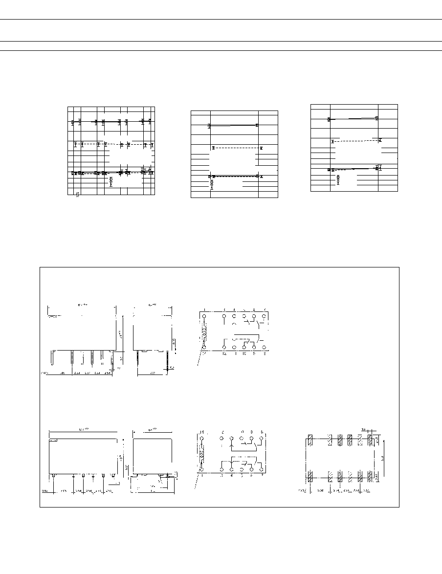
NOT FOR NEW DESIGN
s
DIMENSIONS
q
Dimensions
q
Schematics
(BOTTOM VIEW)
q
PC board mounting
hole layout
(BOTTOM VIEW)
Through hole type
Surface mount type
Orientation mark
Orientation mark
q
Dimensions
q
Schematics
(TOP VIEW)
q
PC board mounting
hole layout
(TOP VIEW)
s
REFERENCE DATA
4.0
3.0
2.0
1.0
0
500
100
200
50
20
10
5
2
1
10
5
50 100
1000
500
Mechanical Life Test
Contact
Resistance (m)
Operation (x10
4
)
Make
Break
FBR-B2MA4.5Z
n=10
1200 operations/min.
Initial
Nominal V
oltage
Multiplying Factor (%)
Operating Voltage
Release Voltage
4.0
3.0
2.0
1.0
0
500
100
200
50
20
10
5
2
10
Electrical Life Test
Contact
Resistance (m)
Operation (x10
4
)
Operating Voltage
Release Voltage
Make
Break
Initial
Nominal V
oltage
Multiplying Factor (%)
FBR-B2MA4.5Z
n=10
30 operations/min.
125 VAC 0.2A
(resistive load)
4.0
3.0
2.0
1.0
0
500
200
100
50
20
10
5
2
5
Electrical Life Test
Contact
Resistance (m)
Operation (x10
4
)
Operating Voltage
Release Voltage
Make
Break
Initial
Nominal V
oltage
Multiplying Factor (%)
FBR-B2MA4.5Z
n=10
30 operations/min.
30 VDC 1A (resistive load)

6
FTR-B2 Series
NOT FOR NEW DESIGN
s
PACKAGING
Dimensions: mm
General tolerance:
Ī
0.2
Quantity of one reel: 250 pieces
Top cover tape
Embossed carrying tape
Perforation
Parts box
Ý 13
Ý 380
Tape feeding
10.7
17.9
32
28.4
14.2
0.4
16
2
4
Ý 1.55
Ý 2.2
11.7
1.75
Reel Dimensions
Tape dimensions
s
RECOMMENDED CONDITION (Temperature Profile)
IRS (Infrared Reflow Soldering)
T
3
T
2
T
1
T
3
= 245
į
C max.
T
2
= 200
į
C max.
T
1
= 165
į
C max.
0
Temperature (
į
C)
soldering
preheating
cooling
120 sec maximum
30 sec
Max.
VPS (Vapor Phase Soldering)
T
3
T
2
T
1
T
3
= 200
į
C maximum
T
2
= 165
į
C maximum
T
1
= 100
į
C maximum
0
Temperature (
į
C)
soldering
preheating
cooling
90 sec Max.
60 sec Max.
60 sec Max.
215
į
C maximum
Note:
1.Temperature profiles show the temperature of PC board surface.
2.Please perform soldering test with your actual PC board before
mass production, since the temperatures of PC board surfaces
vary according to the size of PC board, status of parts mounting
and heating method.

7
FTR-B2 Series
NOT FOR NEW DESIGN
1. General Information
q
Relays produced after the specific date code that is indicated on each data sheet are lead-free
now. Most of our signal and power relays are lead-free. Please refer to Lead-Free Status Info.
(http://www.fcai.fujitsu.com/pdf/LeadFreeLetter.pdf)
q
Lead free solder paste currently used in relays is Sn-3.0Ag-0.5Cu. From February 2005 forward
Sn-3.0Cu-Ni will be used for FTRB3 and FTR-B4 series relays.
q
Most signal and some power relays also comply with RoHS. Please refer to individual data
sheets. Relays that are RoHS compliant do not contain the 6 hazardous materials that
are restricted by RoHS directive (lead, mercury, cadmium, chromium IV, PBB, PBDE).
q
It has been verified that using lead-free relays in leaded assembly process will not cause any
problems (compatible).
q
"LF" is marked on each outer and inner carton. (No marking on individual relays).
q
To avoid leaded relays (for lead-free sample, etc.) please consult with area sales office.
We will ship leaded relays as long as the leaded relay inventory exists.
2. Recommended Lead Free Solder Profile
q
Recommended solder paste Sn-3.0Ag-0.5Cu and Sn-3.0 Cu-Ni (only FTR-B3 and FTR-B4 from February 2005)
RoHS Compliance and Lead Free Relay Information
Reflow Solder condtion
3. Moisture Sensitivity
q
Moisture Sensitivity Level standard is not applicable to electromechanical realys.
4. Tin Whisker
q
SnAgCu solder is known as low riskof tin whisker. No considerable length whisker was found by our in-house
test.
5. Solid State Relays
q
Each lead terminal will be changed from solder plating to Sn plating and Nickel plating. A layer of Nickel plating
is between the terminal and the Sn plating to avoid whisker.
We highly recommend that you confirm your actual solder conditions
Flow Solder condtion:
Pre-heating:
maximum 120įC
Soldering:
dip within 5 sec. at
260įC soler bath
Solder by Soldering Iron:
Soldering Iron
Temperature:
maximum 360įC
Duration:
maximum 3 sec.
max. 120 sec.
90~120 sec.
20~30 sec.
(duration)
Cooling
Pre-heating
Soldering
Peak Temp.: max. 250įC
250
220
130
170
t
em
p
e
r
a
tur
e
(
įC
)

8
FTR-B2 Series
NOT FOR NEW DESIGN
© 2005 Fujitsu Components America, Inc. All company and product names are trademarks or registered trademarks
of their respective owners. Rev. 06/07/2005.
Japan
Fujitsu Component Limited
Gotanda-Chuo Building
3-5, Higashigotanda 2-chome, Shinagawa-ku
Tokyo 141, Japan
Tel: (81-3) 5449-7010
Fax: (81-3) 5449-2626
Email: promothq@ft.ed.fujitsu.com
Web: www.fcl.fujitsu.com
North and South America
Fujitsu Components America, Inc.
250 E. Caribbean Drive
Sunnyvale, CA 94089 U.S.A.
Tel: (1-408) 745-4900
Fax: (1-408) 745-4970
Email: marcom@fcai.fujitsu.com
Web: www.fcai.fujitsu.com
Europe
Fujitsu Components Europe B.V.
Diamantlaan 25
2132 WV Hoofddorp
Netherlands
Tel: (31-23) 5560910
Fax: (31-23) 5560950
Email: info@fceu.fujitsu.com
Web: www.fceu.fujitsu.com
Asia Pacific
Fujitsu Components Asia Ltd.
102E Pasir Panjang Road
#04-01 Citilink Warehouse Complex
Singapore 118529
Tel: (65) 6375-8560
Fax: (65) 6273-3021
Email: fcal@fcal.fujitsu.com
www.fcal.fujitsu.com
Fujitsu Components
International
Headquarter
Offices