 | –≠–ª–µ–∫—Ç—Ä–æ–Ω–Ω—ã–π –∫–æ–º–ø–æ–Ω–µ–Ω—Ç: FTR-B3G | –°–∫–∞—á–∞—Ç—å:  PDF PDF  ZIP ZIP |

1
s
FEATURES
q
These are flat type ultra miniature (SMT), 5.2
±
0.2mm height
(through hole) relays for telecommunication and data
networking equipments, made of high heat resistant material,
which can support IRS and VPS methods.
q
Ultra slim and light weight with a 5.25
±
0.2 mm height and
approximately 0.8 g weight, and an 87mm
2
mounting area.
Most suitable for decreasing size and weight, space saving
and high density packaging of equipment.
q
Contact spring has superb high frequency characteristics.
q
High insulation design conforming to the Bellcore, FCC
standard, with a minimum of 1.6 mm between coil and
contacts insulation distance, an AC 1.5kV coil contact
withstand voltage, and a 2.5kV coil-contact withstand surge
voltage.
q
High efficieny polar electromagnet structure implements
a140mW low coil power consumption. A power saving latch
type is also available.
q
Gold-plated silver alloy bifurcated contacts having high
contact reliability.
q
UL, CSA recognized. Confirms to IEC 60950, UL1950,
EN60950. Spacing & high breakdown voltage (Basic
insulation, 150 working volts, pollution degree 2).
FTR-B3 SERIES
MINIATURE RELAY
2-CONTACT 1A (FOR SWITCHING SIGNALS)

2
FTR-B3 Series
Remarks: Actual marking on relay would not carry code FTR and be as below:
Ordering code
Actual marking
FTR-B3GA012Z-B10
B3GA012Z
s
ORDERING INFORMATION
FTR-B3
G
B
012
Z -B -10
[Example]
(a)
(b) (c)
(d) (e) (f ) (g)
)
a
(
e
m
a
N
s
e
ir
e
S
s
e
ir
e
S
3
B
-
R
T
F
)
b
(
e
p
y
t
l
a
n
i
m
r
e
T
l
a
n
i
m
r
e
t
t
n
u
o
m
e
c
a
f
r
u
s
:
G
)
c
(
n
o
it
c
n
u
f
n
o
it
a
r
e
p
O
e
p
y
t
d
r
a
d
n
a
t
s
:
A
)l
i
o
c
1
(
e
p
y
t
g
n
i
h
c
t
a
l
:
B
)
d
(
li
o
c
f
o
e
g
a
tl
o
v
d
e
t
a
R
C
D
V
5
.
1
:
5
.
1
C
D
V
5
.
4
:
5
.
4
C
D
V
3
:
3
0
C
D
V
2
1
:
2
1
)
e
(
l
a
ir
e
t
a
m
t
c
a
t
n
o
C
y
o
ll
a
r
e
v
li
s
d
e
t
a
l
p
d
l
o
g
:
Z
)
f
(
n
o
it
c
e
ri
d
g
n
i
s
o
l
c
n
e
y
a
l
e
R
n
o
it
c
e
ri
d
g
n
i
s
o
l
c
n
e
d
r
a
d
n
a
t
s
:
B
)
g
(
l
e
e
r
r
e
p
s
y
a
l
e
r
f
o
r
e
b
m
u
N
)
d
r
a
d
n
a
t
s
(
0
0
0
1
:
0
1

3
FTR-B3 Series
L
E
D
O
M
li
o
c
d
e
t
a
R
e
g
a
tl
o
v
e
c
n
a
t
s
i
s
e
r
li
o
C
)
%
0
1
±
(
g
n
it
a
r
e
p
O
e
g
a
tl
o
v
e
s
a
e
l
e
R
*
e
g
a
tl
o
v
r
e
w
o
p
d
e
t
a
R
n
o
it
p
m
u
s
n
o
c
Z
5
.
1
A
)
G
(
3
B
-
R
T
F
C
D
V
5
.
1
1
.
6
1
V
3
1
.
1
+
V
5
1
.
0
+
W
m
0
4
1
Z
3
0
0
A
)
G
(
3
B
-
R
T
F
C
D
V
3
3
.
4
6
V
5
2
.
2
+
V
3
.
0
+
W
m
0
4
1
Z
5
.
4
A
)
G
(
3
B
-
R
T
F
C
D
V
5
.
4
5
4
1
V
8
3
.
3
+
V
5
4
.
0
+
W
m
0
4
1
Z
2
1
0
A
)
G
(
3
B
-
R
T
F
C
D
V
2
1
8
2
0
,
1
V
0
.
9
+
V
2
.
1
+
W
m
0
4
1
s
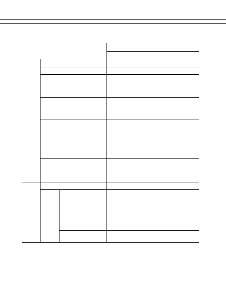
COIL DATA CHART
Standard type
Latching type (1 coil)
* Pulse driven
Note: All values in the table are measured at 20∞C.
* Pulse driven
Note: All values in the table are measured at 20∞C.
s
SAFETY STANDARD AND FILE NUMBERS
UL508, 1950 (File No. E63615)
C22.2 No. 14, No. 950 (File No. LR40304)
Please request when the approval markings are required on the cover.
Nominal voltage
Contact rating
0.5 A
125 VAC
1.5 to 12 VDC
1 A 30 VDC
resistive
0.3 A 110 VDC
L
E
D
O
M
li
o
c
d
e
t
a
R
e
g
a
tl
o
v
e
c
n
a
t
s
i
s
e
r
li
o
C
)
%
0
1
±
(
t
e
S
e
g
a
tl
o
v
e
s
a
e
l
e
R
*
e
g
a
tl
o
v
r
e
w
o
p
d
e
t
a
R
n
o
it
p
m
u
s
n
o
c
Z
5
.
1
B
)
G
(
3
B
-
R
T
F
C
D
V
5
.
1
5
.
2
2
V
3
1
.
1
+
V
3
1
.
1
-
W
m
0
0
1
Z
3
0
0
B
)
G
(
3
B
-
R
T
F
C
D
V
3
0
9
V
5
2
.
2
+
V
5
2
.
2
-
W
m
0
0
1
Z
5
.
4
B
)
G
(
3
B
-
R
T
F
C
D
V
5
.
4
3
0
2
V
8
3
.
3
+
V
8
3
.
3
-
W
m
0
0
1
Z
2
1
0
B
)
G
(
3
B
-
R
T
F
C
D
V
2
1
0
4
4
,
1
V
0
.
9
+
V
0
.
9
-
W
m
0
0
1
4
FTR-B3 Series
s
SPECIFICATIONS
continued
*
1
Minimum switching loads mentioned above are reference values. Please perform the confirmation test with the
actual load before production since reference values may vary according to switching frequencies, environmental
conditions and expected reliability levels.
m
e
t
I
e
p
y
T
d
r
a
d
n
a
t
S
e
p
y
T
g
n
i
h
c
t
a
L
A
)
(
3
B
-
R
T
F
B
)
(
3
B
-
R
T
F
t
c
a
t
n
o
C
t
n
e
m
e
g
n
a
r
r
A
C
m
r
o
F
2
l
a
i
r
e
t
a
m
t
c
a
t
n
o
C
y
o
ll
a
r
e
v
li
s
y
a
l
r
e
v
o
d
l
o
G
e
p
y
t
t
c
a
t
n
o
C
)
r
a
b
-
s
s
o
r
c
(
s
t
c
a
t
n
o
c
d
e
t
a
c
r
u
fi
B
e
c
n
a
t
s
i
s
e
r
t
c
a
t
n
o
C
)
e
u
l
a
v
l
a
it
i
n
i(
m
u
m
i
x
a
m
m
5
7
A
1
C
D
V
6
t
a
g
n
it
a
r
t
c
a
t
n
o
C
A
3
.
0
C
A
V
5
2
1
,
A
1
C
D
V
0
3
t
n
e
r
r
u
c
g
n
i
y
r
r
a
c
m
u
m
i
x
a
M
A
1
r
e
w
o
p
g
n
i
h
c
ti
w
s
m
u
m
i
x
a
M
W
0
3
/
A
V
5
.
2
6
e
g
a
tl
o
v
g
n
i
h
c
ti
w
s
m
u
m
i
x
a
M
C
D
V
0
2
2
,
C
A
V
0
5
2
1
*
d
a
o
l
g
n
i
h
c
ti
w
s
m
u
m
i
n
i
M
*
A
m
1
0
.
0
,
C
D
V
m
0
1
1
e
c
n
a
ti
c
a
p
a
C
)
s
t
c
a
t
n
o
c
n
e
p
o
n
e
e
w
t
e
b
(
F
p
4
.
0
y
l
e
t
a
m
i
x
o
r
p
p
A
)
s
t
c
a
t
n
o
c
t
n
e
c
a
j
d
a
(
F
p
5
.
0
y
l
e
t
a
m
i
o
r
p
p
A
*
F
p
0
.
1
y
l
e
t
a
m
i
x
o
r
p
p
A
1
)
s
t
c
a
t
n
o
c
d
n
a
li
o
c
n
e
e
w
t
e
b
(
li
o
C
)
C
∞
0
2
t
a
(
r
e
w
o
p
l
a
n
i
m
o
N
W
m
0
4
1
W
m
0
0
1
0
C
∞
0
2
t
a
(
r
e
w
o
p
e
t
a
r
e
p
O
W
m
0
8
W
m
7
5
)
t
s
o
r
f
o
n
(
e
r
u
t
a
r
e
p
m
e
t
g
n
it
a
r
e
p
O
C
∞
5
8
+
o
t
C
∞
0
4
-
e
m
i
T
e
u
l
a
V
e
t
a
r
e
p
O
)
e
c
n
u
o
b
t
u
o
h
ti
w
,
e
g
a
tl
o
v
l
a
n
i
m
o
n
t
a
(
m
u
m
i
x
a
m
s
m
3
e
s
a
e
l
e
R
)
e
c
n
u
o
b
t
u
o
h
ti
w
,
e
g
a
tl
o
v
l
a
n
i
m
o
n
t
a
(
m
u
m
i
x
a
m
s
m
3
n
o
it
a
l
u
s
n
I
)
C
D
V
0
0
5
t
a
(
e
c
n
a
t
s
i
s
e
R
M
0
0
0
,
1
m
u
m
i
n
i
M
c
i
r
t
c
e
l
e
i
D
h
t
g
n
e
r
t
S
s
t
c
a
t
n
o
c
n
e
p
o
n
e
e
w
t
e
b
e
t
u
n
i
m
1
C
A
V
0
0
0
,
1
s
t
c
a
t
n
o
c
t
n
e
c
a
j
d
a
n
e
e
w
t
e
b
e
t
u
n
i
m
1
C
A
V
0
0
0
,
1
s
t
c
a
t
n
o
c
d
n
a
li
o
c
n
e
e
w
t
e
b
e
t
u
n
i
m
1
C
A
V
0
0
5
,
1
e
g
r
u
S
h
t
g
n
e
r
t
S
s
t
c
a
t
n
o
c
n
e
p
o
n
e
e
w
t
e
b
]
8
6
t
r
a
P
C
C
F
[
)
s
µ
0
6
1
x
0
1
t
a
(
V
0
0
5
,
1
s
t
c
a
t
n
o
c
t
n
e
c
a
j
d
a
n
e
e
w
t
e
b
]
8
6
t
r
a
P
C
C
F
[
)
s
µ
0
6
1
x
0
1
t
a
(
V
0
0
5
,
1
s
t
c
a
t
n
o
c
d
n
a
li
o
c
n
e
e
w
t
e
b
]
8
6
t
r
a
P
C
C
F
[
)
s
µ
0
6
1
x
0
1
t
a
(
V
0
0
5
,
1
]
e
r
o
c
ll
e
B
[
)
s
µ
0
1
x
2
t
a
(
V
0
0
5
,
2
5
FTR-B3 Series
s
SPECIFICATIONS
continued
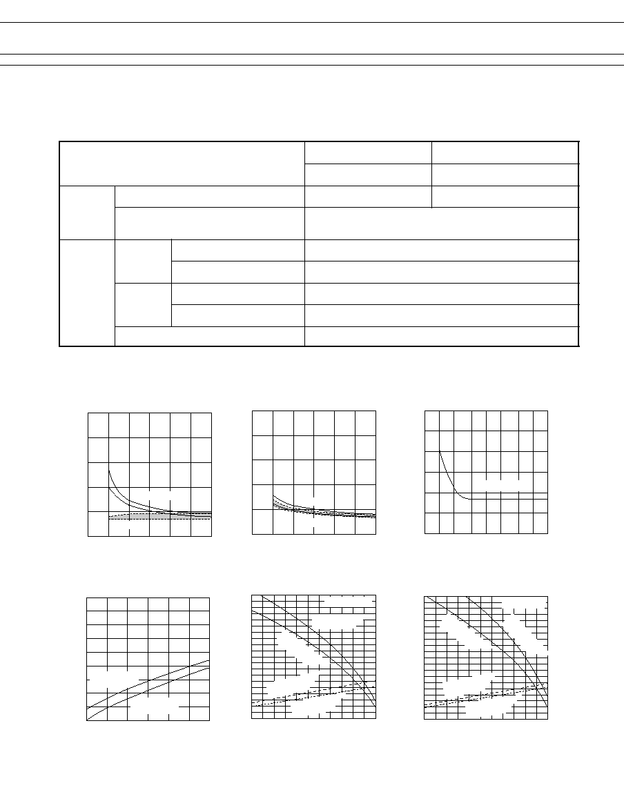
s
CHARACTERISTIC DATA
,
5
4
3
2
1
0
0.1
0.2
0.3
Operation
(return time characteristics)
T
ime (ms)
Release
Operation time
Coil Power (W)
5
4
3
2
1
0
0.1
0.2
0.3
,,
Set, reset time characteristics
T
ime (ms)
Set time
Reset time
Coil Power (W)
100
90
80
70
60
50
40
0.5
1
2
5
10
20
50
100 200
Pulse characteristics
Nominal V
oltage Multiplying Factor (%)
Pulse width (ms)
At set/reset
80
60
40
20
0
0
0.1
0.2
0.3
Coil Temperature Rise
Coil
T
emperature Rise (∞C)
Coil Power (W)
Contact carrying
current: 1A
Contact carrying
current: 0
2.4
2.2
2.0
1.8
1.6
1.4
1.2
1.0
0.8
0.6
0
20
40
60
80
100
Ambient Temperature
(maximum applied voltage,
operating voltage characteristics)
Nominal V
oltage Multiplying Factor (%)
Ambient Temperature (∞C)
Standard type
Contact carrying
current: 0
Contact carrying
current: 1A
Operating voltage
(hot coil)
Operating voltage
(cool coil)
2.4
2.2
2.0
1.8
1.6
1.4
1.2
1.0
0.8
0.6
0
20
40
60
80
100
Ambient Temperature
(maximum applied voltage,
operating voltage characteristics)
Nominal V
oltage Multiplying Factor
Ambient Temperature (∞C)
Contact carrying
current: 1A
Contact carrying
current: 1A
Latching Type
Operating V
oltage
(hot coil)
Operating V
oltage
(cool coil)
continued
m
e
t
I
e
p
y
T
d
r
a
d
n
a
t
S
e
p
y
T
g
n
i
h
c
t
a
L
A
)
(
3
B
-
R
T
F
B
)
(
3
B
-
R
T
F
e
f
i
L
l
a
c
i
n
a
h
c
e
M
0
1
x
0
5
6
.
n
i
m
s
n
o
it
a
r
e
p
o
)
z
H
3
t
a
(
0
1
x
0
2
6
.
n
i
m
s
n
o
i
t
a
r
e
p
o
)
z
H
3
t
a
(
)
d
a
o
l
e
v
i
t
s
i
s
e
r
(
l
a
c
i
r
t
c
e
l
E
0
1
x
0
0
1
3
)
z
H
5
.
0
t
a
(
C
D
V
0
3
A
1
t
a
.
n
i
m
s
n
o
i
t
a
r
e
p
o
0
1
x
0
0
1
3
)
z
H
5
.
0
t
a
(
C
D
V
5
2
1
A
3
.
0
t
a
.
n
i
m
s
n
o
i
t
a
r
e
p
o
r
e
h
t
O
n
o
i
t
a
r
b
i
V
e
c
n
a
t
s
i
s
e
r
n
o
i
t
c
n
u
f
l
a
M
m
m
3
.
3
f
o
e
d
u
t
il
p
m
a
e
l
b
u
o
d
t
a
z
H
5
5
o
t
0
1
e
c
n
a
r
u
d
n
E
m
m
5
f
o
e
d
u
t
il
p
m
a
e
l
b
u
o
d
t
a
z
H
5
5
o
t
0
1
k
c
o
h
S
e
c
n
a
t
s
i
s
e
r
n
o
i
t
c
n
u
f
l
a
M
s
/
m
0
5
7
.
n
i
M
2
e
c
n
a
r
u
d
n
E
s
/
m
0
0
0
1
.
n
i
M
2
t
h
g
i
e
W
g
8
.
0
y
l
e
t
a
m
i
x
o
r
p
p
A
6
FTR-B3 Series
continued
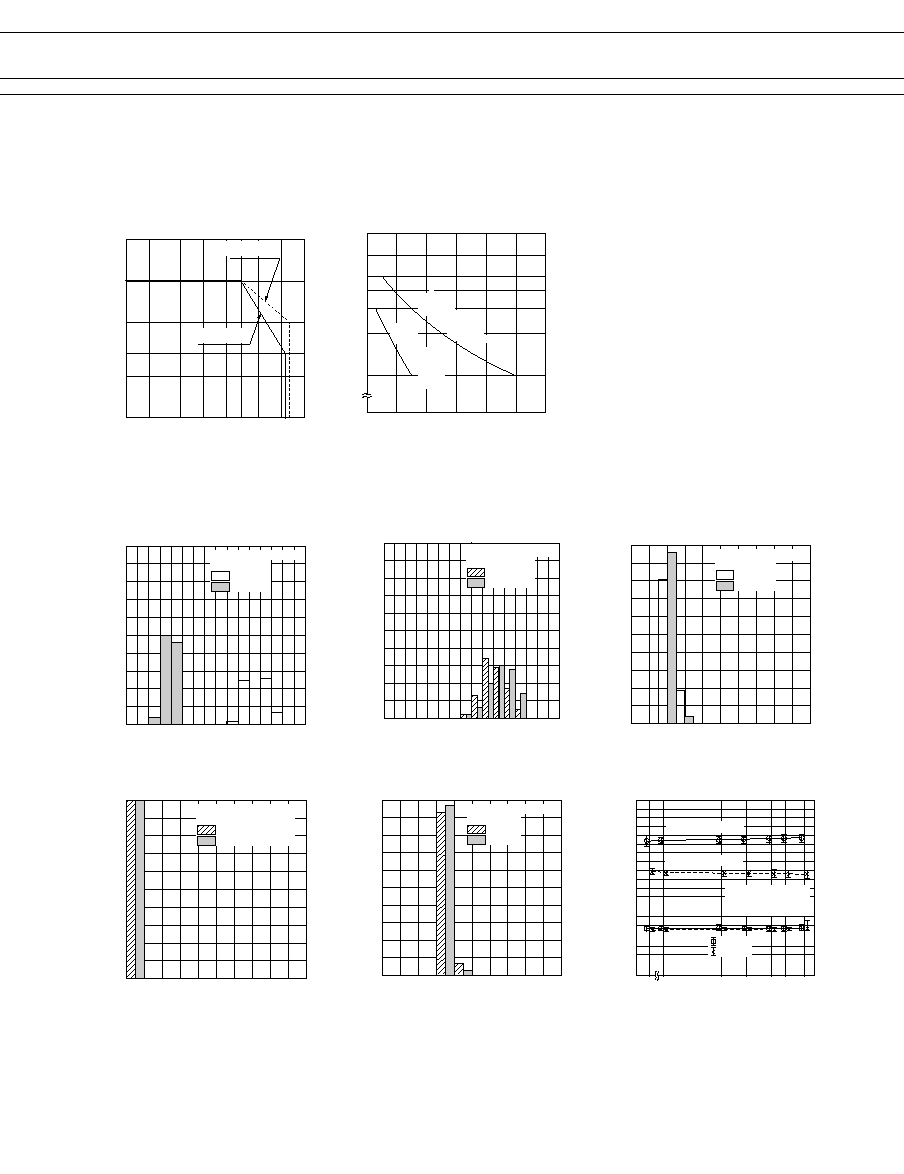
s
CHARACTERISTIC DATA
2
1
0.5
0.3
0.2
0.1
1
2
5
10
20 30 50
100 200
Maximum Switching Power
Contact Current (A)
Contact Voltage (V)
AC Resistive
DC Resistive
100
70
50
40
30
20
10
0
0.2
0.4
0.6
0.8
1.0
1.2
Life Curve
Operation (x10
4
)
Contact Current (A)
30 VDC Resistive
125 VDC Resistive
s
REFERENCE DATA
100
80
60
40
20
0
10
20
30
40
50
60
70
80
~
~
Q
~
Q
~
Q
|
~
z
Distribution of Operate
and Release Voltage
Distribution (%)
Nominal Voltage Multiplying Factor (%)
FTR-B3GA4.5Z
n=100
Operate
Release
100
80
60
40
20
0
10
20
30
40
50
60
70
80
Distribution of Operate
and Release Voltage
Distribution (%)
Nominal Voltage Multiplying Factor (%)
FTR-B3GB4.5Z
n=100
Operate
Release
100
80
60
40
20
0
1
2
3
4
5
P
Q
,
y
z
|
P
z
Distribution of Operate
and Release Time
Distribution (%)
Time (ms)
FTR-B3GA4.5Z
n=100
Operate
Release
100
80
60
40
20
0
1
2
3
4
5
Distribution of Bounce Time
Distribution (%)
FTR-B3GA4.5Z
N=100
Operate
Release
Time (ms)
100
80
60
40
20
0
20
40
60
80
100
Distribution of Contact Resistance
Distribution (%)
FTR-B3GA4.5Z
n=100
Make
Break
Contact Resistance (m)
100
80
60
40
20
0
500
100
50
10
5
100
500 1000
2000 3000 5000
Mechanical Life Test
Contact Resistance (m)
Operation (x10
4
)
Operating Voltage
Release Voltage
Make
Break
FTR-B3GA4.5Z
n=8
1200 operations/min.
Initial
continued

7
FTR-B3 Series
1
2
3
4
8
7
6
5
(+)
(-)
Marking
(Coil side indication)
5.08±0.2
0.2
+0.2
3
.
5
+
0.
3
-
0.
2
0.
5
±
0.0
5
0.4
+0.2
3.2
±0.2
2.2
±0.2
2.2
±0.2
(1.5)
3.2
2.2
2.2
5
.0
8
8-ÿ0.85
5
.
2
±
0.0
2
10.6
±0.2
7.2
±0.2
s
SPECIFICATIONS
continued
100
80
60
40
20
0
500
100
50
10
5
1
10
Electrical Life Test
Contact
Resistance (m)
Operation (x10
4
)
Operating Voltage
Release Voltage
Make
Break
FTR-B3GA4.5Z
n=8
30 operations/min.
126 VAC 0.3 A
(resistive load)
Initial
Nominal V
oltage
Multiplying Factor (%)
100
80
60
40
20
0
500
100
50
10
5
1
10
Electrical Life Test
Contact
Resistance (m)
Operation (x10
4
)
Operating Voltage
Release Voltage
Make
Break
Initial
Nominal V
oltage
Multiplying Factor (%)
FTR-B3GA4.5Z
n=8
30 operations/min.
30 VAC 1A
(resistive load)
20
10
0
-10
-20
20
10
0
-10
-20
0
2
4
6
8
10
Magnetic Interference
Distance between relays I (mm)
Operating Voltage
Release Voltage
When coil
is ON
When coil
is OFF
Nominal V
oltage
Multiplying Factor (%)
FTR-B3GA4.5Z
n=4
Nominal V
oltage
Multiplying Factor (%)
Standard
type
20
10
0
-10
-20
20
10
0
-10
-20
0
2
4
6
8
10
Magnetic Interference
Distance between relays I (mm)
Operating Voltage
Release Voltage
When coil
is ON
When coil
is OFF
Nominal V
oltage
Multiplying Factor (%)
FTR-B3GA4.5Z
n=4
Nominal V
oltage
Multiplying Factor (%)
Standard
type
150
100
50
0
1
3
5 7 10
30 50 70 100
300 500 700 1000
High Frequency Characteristics
Frequency (MHz)
FTR-B3GA4.5Z
n=2
Isolation (dB)
1.8
1.6
1.4
1.2
1.0
0.8
0.6
0.4
0.2
0
1
10
30 50 70
3
5 7
1000
100
300 500700
High Frequency Characteristics
Frequency (MHz)
FTR-B3GA4.5Z
n=2
Insertion Loss (dB)
s
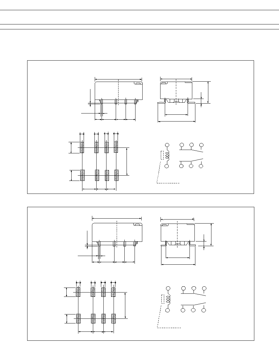
DIMENSIONS
q
Dimensions
Unit: mm
q
Mounting Pad
(TOP VIEW)
q
Wiring Diagram
(TOP VIEW)
FTR-B3C( )( )( )
8
FTR-B3 Series
1
2
3
4
8
7
6
5
(+)
(-)
Marking
(Coil side indication)
5.08±0.2
8.2
+0.5
-0.3
1
.0
5
0.4
+0.2
3.2
±0.2
2.2
±0.2
2.2
±0.2
(1.5)
3.2
2.2
2.2
5
.
2
5
±
0.0
2
0.
2
+
0.
2
2
.
5
6
2
.
5
6
6
.
6
4
0.8
0.8
0.8
0.8
10.6
±0.2
7.2
±0.2
s
DIMENSIONS
q
Dimensions
Unit: mm
q
Mounting Pad
(TOP VIEW)
q
Wiring Diagram
(TOP VIEW)
FTR-B3G( )( )( )
q
Dimensions
Unit: mm
q
Mounting Pad
(TOP VIEW)
q
Wiring Diagram
(TOP VIEW)
FTR-B3S( )( )( )
1
2
3
4
8
7
6
5
(+)
(-)
Marking
(Coil side indication)
5.08±0.2
7.2
+0.5
-0.3
1
.0
5
0.4
+0.2
3.2
±0.2
2.2
±0.2
2.2
±0.2
(1.5)
3.2
2.2
2.2
5
.
2
5
±
0.0
2
0.
2
+
0.
2
2
.0
8
2
.0
8
6
.
1
4
0.8
0.8
0.8
0.8
10.6
±0.2
7.2
±0.2

9
FTR-B3 Series
s
PACKAGING SPECIFICATIONS
q
Packaging Method
- Packaging Standard: JIS C 0806
- Taping Type: TB 1612
- Reel Type: R16D
- Quantity of 1reel: 1000 pieces
q
Packaging Orientation Code:B
Orientation mark side
Feeding
q
(2) Dimensions
- Reel dimensions
Top cover tape
Embossed carrier tape
q
Tape Dimensions
Note: Relays are sold in packs of 1000 pieces,
please order 1000 pieces as one unit.
Unit: mm
s
RECOMMENDED SOLDERING CONDITIONS
(TEMPERATURE PROFILE)
IRS (Infrared Reflow Soldering)
T
3
T
2
T
1
T
3
= 245
∞
C max.
T
2
= 200
∞
C max.
T
1
= 165
∞
C max.
0
Temperature (
∞
C)
soldering
preheating
cooling
120 sec maximum
30 sec
Max.
VPS (Vapor Phase Soldering)
T
3
T
2
T
1
T
3
= 200
∞
C maximum
T
2
= 165
∞
C maximum
T
1
= 100
∞
C maximum
0
Temperature (
∞
C)
soldering
preheating
cooling
90 sec Max.
60 sec Max.
60 sec Max.
215
∞
C maximum
Note:
1.Temperature profiles show the temperature of PC board surface.
2.Please perform soldering test with your actual PC board before
mass production, since the temperatures of PC board surfaces
vary according to the size of PC board, status of parts mounting
and heating method.

10
FTR-B3 Series
s
PRECAUTIONS
- For details on general precautions, refer to the section on technical descrip-
tions.
- Since this is a polar relay, follow the instructions of the internal wiring
diagram for the +- connections of the coil.
- Note that the terminal array and internal wiring of the surface mount relay
are a top view
© 2003 Fujitsu Components America, Inc. All company and product names are trademarks or registered trademarks
of their respective owners. Rev. 06/27/2003
Japan
Fujitsu Component Limited
Gotanda-Chuo Building
3-5, Higashigotanda 2-chome, Shinagawa-ku
Tokyo 141, Japan
Tel: (81-3) 5449-7010
Fax: (81-3) 5449-2626
Email: promothq@ft.ed.fujitsu.com
Web: www.fcl.fujitsu.com
North and South America
Fujitsu Components America, Inc.
250 E. Caribbean Drive
Sunnyvale, CA 94089 U.S.A.
Tel: (1-408) 745-4900
Fax: (1-408) 745-4970
Email: marcom@fcai.fujitsu.com
Web: www.fcai.fujitsu.com
Europe
Fujitsu Components Europe B.V.
Diamantlaan 25
2132 WV Hoofddorp
Netherlands
Tel: (31-23) 5560910
Fax: (31-23) 5560950
Email: info@fceu.fujitsu.com
Web: www.fceu.fujitsu.com
Asia Pacific
Fujitsu Components Asia Ltd.
102E Pasir Panjang Road
#04-01 Citilink Warehouse Complex
Singapore 118529
Tel: (65) 375-8560
Fax: (65) 273-3021
Email: fcal@fcal.fujitsu.com
www.fcal.fujitsu.com
Fujitsu Components
International
Headquarter
Offices